
Page 98 - Finite Element Modeling and Simulations with ANSYS Workbench
P. 98
Beams and Frames 83
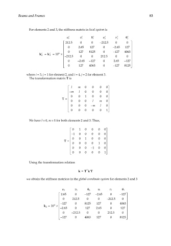
For elements 2 and 3, the stiffness matrix in local system is
u i ′ v i ′ i ′ θ u j ′ v j ′ j ′ θ
212 5 . 0 0 −212 5 . 0 0
5
.
0 2 65 127 0 −2 6 . 5 127
0 127 8125 0 − 127 4063
k 2 ′ = k 3 ′ = 10 4 ×
− 212 5 . 0 0 212 5 . 0 0
0 − . − 127 0 2 65 − 127
.
2 65
0 1227 4063 0 − 127 8125
where i = 3, j = 1 for element 2, and i = 4, j = 2 for element 3.
The transformation matrix T is
l m 0 0 0 0
−m l 0 0 0 0
0 0 1 0 0 0
T =
0 0 0 l m 0
0 0 0 −m l 0
0 0 0 0 0 1
We have l = 0, m = 1 for both elements 2 and 3. Thus,
0 1 0 0 0 0
−1 0 0 0 0 0
0 0 1 0 0 0
T =
0 0 0 0 1 0
0 0 0 −1 0 0
0 0 0 0 0 1
Using the transformation relation
T
k = T kT ′
we obtain the stiffness matrices in the global coordinate system for elements 2 and 3
3 θ 1 θ
u 3 v 3 u 1 v 1
.
265
265 0 − 127 − . 0 − 127
0 212 5 . 0 0 − 212 5 . 0
− 127 0 8 8125 127 0 4063
4
k 2 = 10 ×
.
265
− . 0 127 265 0 127
0 − 212 5 . 0 0 212 5 . 0
− 127 0 4063 127 0 8 8125 