
Page 100 - Finite Element Modeling and Simulations with ANSYS Workbench
P. 100
Beams and Frames 85
and
F X4 − 2338 lb
F Y4 = 3825 lb
112 641lb in.
⋅
,
M 4
Check the results: Draw the free-body diagram of the frame as shown below. Equilibrium
is maintained with the calculated forces and moments. Recall that the problem we
solved is the one with the equivalent loads, not the one with the distributed load. Thus,
the corresponding FBD for the FE model should be applied for verifying the results.
3000 lb 3000 lb
72,000 lb-in.
3000 lb
72,000 lb-in.
60,364 lb-in. 112,641 lb-in.
672.7 lb 2338 lb
2210 lb 3825 lb
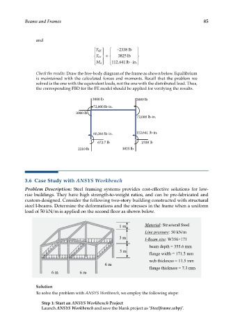
3.6 Case Study with ANSYS Workbench
Problem Description: Steel framing systems provides cost-effective solutions for low-
rise buildings. They have high strength-to-weight ratios, and can be pre-fabricated and
custom-designed. Consider the following two-story building constructed with structural
steel I-beams. Determine the deformations and the stresses in the frame when a uniform
load of 50 kN/m is applied on the second floor as shown below.
Solution
To solve the problem with ANSYS Workbench, we employ the following steps:
Step 1: Start an ANSYS Workbench Project
Launch ANSYS Workbench and save the blank project as ‘Steelframe.wbpj’.