
Page 91 - Finite Element Modeling and Simulations with ANSYS Workbench
P. 91
76 Finite Element Modeling and Simulation with ANSYS Workbench
3.5 Examples with Beam Elements
EXAMPLE 3.1
y
P
1 M 2
1 E, I 2 3 x
L L
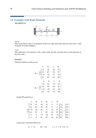
Given:
The beam shown above is clamped at the two ends and acted upon by the force P and
moment M in the midspan.
Find:
The deflection and rotation at the center node and the reaction forces and moments at
the two ends.
Solution
Element stiffness matrices are
1 θ 2 θ
v 1 v 2
12 6 L − 12 6 L
EI 6 L 4 L 2 − 6 L 2 L 2
k 1 = L − 12 − 6 L 12 − 6 L
3
2 2
6 L 2 L − 6 L 4 L
v 2 θ 2 v 3 θ 3
12 6 L −12 6 L
EI 6 L 4 L 2 − L6 2 L 2
2 k = L −12 − L6 12 −6L
3
6
2 − 2
6L 2L 6L 4L
Global FE equation is
1 θ 2 θ 3 θ
v 1 v 2 v 3
v
12 6 L − 12 6 L 0 0 v 1 F Y
1
2 − 2
6 L 4 L 6 L 2 L 0 0 1 θ M 1
EI − 12 − 6 L 24 0 − 12 6 L v 2 F Y
2
L 3 6 L 2 L 2 2 0 8L 2 − 6L 2L 2 2 θ = M 2
0 0 − 12 − 6L 12 − 6L
2 2 v 3 F Y
3
3
0 0 6L 2L − 6L 4L θ M 3
Loads and constraints (BCs) are
F Y2 =− P, M 2 = M, v 1 = v 3 =θ =θ = 0
3
1