Page 92 - Finite Element Modeling and Simulations with ANSYS Workbench
P. 92

Beams and Frames                                                             77


                  Reduced FE equation


                                         EI 24   0  v 2    − P
                                           
                                                             
                                                      2 θ 
                                         L 3    0  8 L 2   =  M 
                                                    
                                                          
                                                             

                  Solving this, we obtain
                                             v 2   L   − PL  
                                                          2
                                              =  24    
                                             2 θ 
                                                      
                                                 EI   3 M  
                  From the global FE equation, we obtain the reaction forces and moments
                                                                 3 /
                                  F Y1    − 12  6 L     P  + M L 
                                                            2
                                               2                
                                  M 1  EI − 6 L  2 L    1  PL  + M  
                                                   
                                          
                                                     v 2
                                    =  3            =           
                                                                 3 /
                                                     
                                   F Y   L   − 12  − 6 L θ   4 2 P  − M L 
                                                            
                                   3
                                                      2
                                                  2 
                                  M 3    6 L  2 L         −PL  + M  
                                                                
                  Stresses in the beam at the two ends can be calculated using the formula
                                                       My
                                             σ= σ= −
                                                  x
                                                        I
                  Note that the FE solution is exact for this problem according to the simple beam
                   theory, since no distributed load is present between the nodes. Recall that
                                                  4
                                                 dv
                                              EI  4  =  qx()
                                                dx
                  If q(x) = 0, then exact solution for the deflection v is a cubic function of x, which is
                 exactly what described by the shape functions given in Equation 3.6.
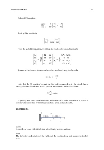
                 EXAMPLE 3.2
                                         y        p

                                         1          E, I   2   x
                                                  L

                 Given:
                 A cantilever beam with distributed lateral load p as shown above.

                 Find:
                 The deflection and rotation at the right end, the reaction force and moment at the left
                 end.
   87   88   89   90   91   92   93   94   95   96   97