
Page 82 - Finite Element Modeling and Simulations with ANSYS Workbench
P. 82
Beams and Frames 67
the neutral axis. For a Timoshenko beam, both the vertical displacement (v) and the rota-
tion angle of beam cross section (θ) are needed for a complete description of its deformed
configuration.
3.2.2 Stress, Strain, Deflection, and Their Relations
Simple beam bending is often analyzed using the Euler–Bernoulli beam theory, which is
popular in engineering owing to its simplicity and is referred to as the engineering beam
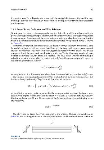
theory by many. To understand the stress state in simple beam bending, imagine that the
beam is made of many infinitesimally thin layers deposited on top of each other, as shown
in Figure 3.4.
Under the assumption that the neutral axis does not change in length, the material layer
located along the axis will stay stress free. However, the beam will bend concave upward
to resist a downward transverse load. Bending makes layers above the neutral axis axially
compressed and the ones underneath axially stretched. The further away a material layer
is from the neutral axis, the more it is strained. The axial strain induced by bending is
called the bending strain, which is related to the deflected beam curvature κ(x) based on
differential geometry as follows:
2
dv
ε() = −κ() =−y (3.1)
x
y
x
dx 2
where y is the vertical distance of a thin layer from the neutral axis and v the beam deflection.
The internal resisting bending moment M(x) is a function of the axial bending stress σ(x)
from the theory of elasticity. Together with Equation 3.1, we have:
2
Mx() = ∫ − y () ∫ Ey κ () EI () = EI dv (3.2)
σ
x dA =
κ
xdA =
2
x
dx 2
where E is the material elastic modulus, I is the area moment of inertia of the beam cross-
section with respect to the z-axis, and the product of E and I is called the bending stiffness.
Combining Equations 3.1 and 3.2, we arrive at the following flexure formula for the bend-
ing stress σ(x):
Mx
()y
σ() = − (3.3)
x
I
The above simple beam theory is analogous to the uniaxial Hooke’s law. As shown in
Table 3.1, the bending moment is linearly proportional to the deflected beam curvature
y
x
FIGURE 3.4
Bending produces axial stress σ(x) along thin material layers in a beam.