
Page 105 - Flexible Robotics in Medicine
P. 105
90 Chapter 4
this stage. Table 4.1 recapitulates part of the metrics table. The left side of the table is taken
from the metrics part of the needs-metrics matrix, while the right side correspondingly
summarizes the design process if the metric was considered during the design process, and
it was measured within the scope here.
4.3.5.1 Easy manipulation around corners
One of the key features of an actively actuated endoscope forceps is the ease of use from
the operator’s point of view. The flexible forceps must be able to navigate corners easily
within a short time frame. Transmitting force through cables allows precise control of speed
via the programming of the stepper motors. The current prototyped proximal control
(Fig. 4.9) is a large, upscaled version, but the final prototype is expected to fit into the palm
of an operator (Fig. 4.11).
Table 4.1: Metrics and design consideration.
Design considerations
Needs-metrics matrix
Metric Importance Units Considered Measured
Easy manipulation around corners 2 min ü ü
Stability of the prototypes (tips, forceps) 1 N ü ü
Cost 5 $ 3 3
Strength of jaw (pull out) 1 N ü 3
Strength of distal tip 1 N ü ü
Strength of forceps 1 N ü 3
Accuracy of prototype 1 mm/% ü ü
Biocompatibility 3 Yes/No ü 3
Size of prototype 2 mm ü ü
In-clinic preparation time 3 min 3 3
Durability and life span 4 Years 3 3
Total bending angle 2 Degrees ü ü
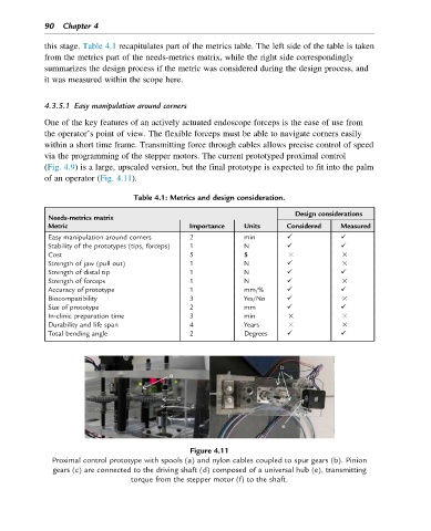
Figure 4.11
Proximal control prototype with spools (a) and nylon cables coupled to spur gears (b). Pinion
gears (c) are connected to the driving shaft (d) composed of a universal hub (e), transmitting
torque from the stepper motor (f) to the shaft.