
Page 197 - Flexible Robotics in Medicine
P. 197
184 Chapter 7
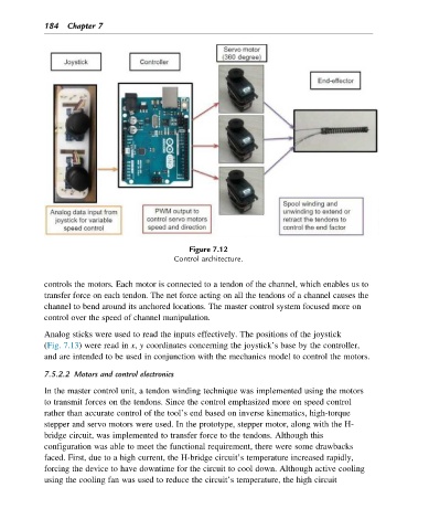
Figure 7.12
Control architecture.
controls the motors. Each motor is connected to a tendon of the channel, which enables us to
transfer force on each tendon. The net force acting on all the tendons of a channel causes the
channel to bend around its anchored locations. The master control system focused more on
control over the speed of channel manipulation.
Analog sticks were used to read the inputs effectively. The positions of the joystick
(Fig. 7.13) were read in x, y coordinates concerning the joystick’s base by the controller,
and are intended to be used in conjunction with the mechanics model to control the motors.
7.5.2.2 Motors and control electronics
In the master control unit, a tendon winding technique was implemented using the motors
to transmit forces on the tendons. Since the control emphasized more on speed control
rather than accurate control of the tool’s end based on inverse kinematics, high-torque
stepper and servo motors were used. In the prototype, stepper motor, along with the H-
bridge circuit, was implemented to transfer force to the tendons. Although this
configuration was able to meet the functional requirement, there were some drawbacks
faced. First, due to a high current, the H-bridge circuit’s temperature increased rapidly,
forcing the device to have downtime for the circuit to cool down. Although active cooling
using the cooling fan was used to reduce the circuit’s temperature, the high circuit