
Page 235 - Flexible Robotics in Medicine
P. 235
Tendon-driven linkage for steerable guide of flexible bending manipulation 223
9.3.2 Experimental procedure
The aim of this experiment is to identify the stability of the drill-guide system during
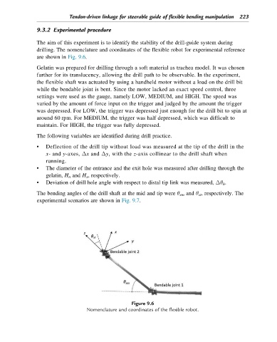
drilling. The nomenclature and coordinates of the flexible robot for experimental reference
are shown in Fig. 9.6.
Gelatin was prepared for drilling through a soft material as trachea model. It was chosen
further for its translucency, allowing the drill path to be observable. In the experiment,
the flexible shaft was actuated by using a handheld motor without a load on the drill bit
while the bendable joint is bent. Since the motor lacked an exact speed control, three
settings were used as the gauge, namely LOW, MEDIUM, and HIGH. The speed was
varied by the amount of force input on the trigger and judged by the amount the trigger
was depressed. For LOW, the trigger was depressed just enough for the drill bit to spin at
around 60 rpm. For MEDIUM, the trigger was half depressed, which was difficult to
maintain. For HIGH, the trigger was fully depressed.
The following variables are identified during drill practice.
• Deflection of the drill tip without load was measured at the tip of the drill in the
x-and y-axes, Δx and Δy, with the z-axis collinear to the drill shaft when
running.
• The diameter of the entrance and the exit hole was measured after drilling through the
gelatin, H n and H x , respectively.
• Deviation of drill hole angle with respect to distal tip link was measured, Δθ h .
The bending angles of the drill shaft at the mid and tip were θ sm and θ st , respectively. The
experimental scenarios are shown in Fig. 9.7.
Figure 9.6
Nomenclature and coordinates of the flexible robot.