
Page 237 - Flexible Robotics in Medicine
P. 237
Tendon-driven linkage for steerable guide of flexible bending manipulation 225
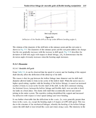
Figure 9.8
Deflection of the flexible drill at the tip under different bending angles θ s .
The relation of the diameter of the drill hole at the entrance point and the exit point is
shown in Fig. 9.9. The diameters of the entrance point and the exit point address the change
that the size gradually increases with the increase in drill speed. Fig. 9.10 describes the
deviation of drill hole angle with respect to distal linkage, Δθ h . It demonstrates that the
deviation angle obviously increases when the bending angle increases.
9.3.4 Discussion
9.3.4.1 Bendable drill guide
From Table 9.2, it can be observed that the speed of a motor and the bending of the support
shaft directly affect the deflection of the distal tip of the drill.
The reason is that the gap between the hollow linkage inner diameter and the drill shaft
diameter allowed kinks to form in the cavity of the hollow shaft. When the motor ran at a
higher speed setting, together with the bending of the hollow linkage, it caused an increased
number of kinks to occur in the flexible shaft of the drill. As the drill continued rotating,
the frictional forces, between the hollow linkage and flexible shaft, were not able to hold
the kinks in a fixed place. The elastic drill shaft thus eccentrically moved and caused
jerking in the entire system. The repetitive jerking destabilized the support and increased
the deflection with respect to lower speed settings and lower bending.
It was further observable that the deflections in the x-axis, Δx, were generally greater than
those in the y-axis, Δy, except the bending angle is 0 degree at LOW drill speed. This was
due to the structure of the mechanical linkages, whereby the bending of the hollow linkage
causes the drill shaft to lean toward the x-axis and rotary along y-axis. The elasticity in the