
Page 264 - Flexible Robotics in Medicine
P. 264
Comparative mechanical analysis for flexible bending manipulators 253
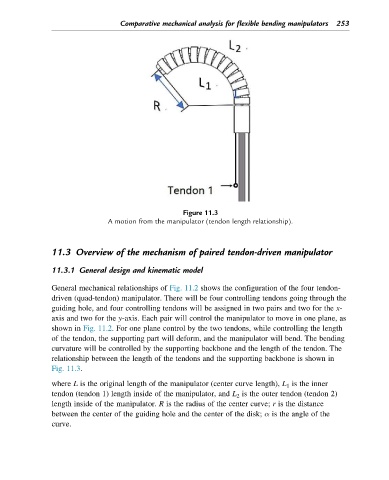
Figure 11.3
A motion from the manipulator (tendon length relationship).
11.3 Overview of the mechanism of paired tendon-driven manipulator
11.3.1 General design and kinematic model
General mechanical relationships of Fig. 11.2 shows the configuration of the four tendon-
driven (quad-tendon) manipulator. There will be four controlling tendons going through the
guiding hole, and four controlling tendons will be assigned in two pairs and two for the x-
axis and two for the y-axis. Each pair will control the manipulator to move in one plane, as
shown in Fig. 11.2. For one plane control by the two tendons, while controlling the length
of the tendon, the supporting part will deform, and the manipulator will bend. The bending
curvature will be controlled by the supporting backbone and the length of the tendon. The
relationship between the length of the tendons and the supporting backbone is shown in
Fig. 11.3.
where L is the original length of the manipulator (center curve length), L 1 is the inner
tendon (tendon 1) length inside of the manipulator, and L 2 is the outer tendon (tendon 2)
length inside of the manipulator. R is the radius of the center curve; r is the distance
between the center of the guiding hole and the center of the disk; α is the angle of the
curve.