
Page 269 - Flexible Robotics in Medicine
P. 269
258 Chapter 11
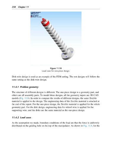
Figure 11.10
Load case for one-piece design.
Disk-wire design is used as an example of the FEM setting. The rest designs will follow the
same setting as the disk-wire design.
11.4.1 Problem geometry
The structure of different designs is different. The one-piece design is a geometry part, and
others are all assembly parts. To model these designs, all the geometry inputs are 3D CAD
models (Fig. 11.8). In order to compare the results of different designs, the same flexible
material is applied to the design. The engineering data of the flexible material is attached at
the end of the report. For the one-piece design, the flexible material is applied for the whole
geometry part. For the disk design, engineering data for nitinol wire is applied for the
supporting wire, and the disks are the same material as the one-piece design.
11.4.2 Load cases
As the assumption we made, boundary conditions of the load are that the force is uniformly
distributed on the guiding hole on the top of the manipulator. As shown in Fig. 11.9, for the