
Page 266 - Flexible Robotics in Medicine
P. 266
Comparative mechanical analysis for flexible bending manipulators 255
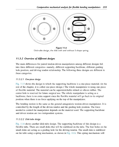
Figure 11.6
Disk-tube design, the disk with and without S-shape spring.
11.3.2 Overview of different designs
The main differences for paired tendon-driven manipulators among different designs fall
into three different categories—namely, different supporting backbone, different guiding
hole position, and driving tendon relationship. The following three designs are different in
these categories.
11.3.2.1 One-piece design
Fig. 11.5 shows the design in which the supporting backbone is a one-piece material. (in the
rest of the chapter, it is called one-piece design.) The whole manipulator is using one piece
of flexible material. The material can be superstretchable nitinol or silicon rubber. The
center hole is reserved for future surgical use. The whole manipulator is acting as a
backbone; there is no extra support since the flexible material will go back to its original
position when there is no force applying on the top of the manipulator.
The bending motion is the same as the general antagonistic tendon-driven manipulator. It is
controlled by the length of the driven tendon and the guiding hole position. The force
needed to control the manipulator depends on the material used. The supporting backbone
and driven tendon are two independent systems.
11.3.2.2 Disk-tube design
Fig. 11.6 shows another disk-tube design. The supporting backbone of this design is a
flexible tube. There are small disks that will be stabilized on the tube. The four holes on the
small disks are acting as a guiding hole for the driving tendon. The small disk is stabilized
on the tube using a spring mechanism, as shown in Fig. 11.6. This spring mechanism will