
Page 267 - Flexible Robotics in Medicine
P. 267
256 Chapter 11
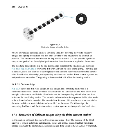
Figure 11.7
Disk-wire design with the disks.
be able to stabilize the small disks at the same time, not affecting the whole structure
design. The spring mechanism will not limit the size of the structure to be as small as
possible. The structure of the tube can be any elastic material if it can provide significant
support and go back to the original position when there is no force applied to the tendon.
The disk-tube design looks like the one-piece design except for the small disk, as shown in
Fig. 11.6. Fig. 11.6A and B shows the disk with and without the s-shape spring. There is a gap
in the disk, and it can fit in the s-shape spring so that the disk can be stabilized on the flexible
tube. For this disk-tube design, the supporting backbone and tendon-driven control systems are
independent of each other. The guiding hole on the disk will affect the bending motion.
11.3.2.3 Disk-wire design
Fig. 11.7 shows the disk-wire design. In this design, the supporting backbone is a
superstretchable wire. There are small disks that will be stabilized on the wire. There will
be eight holes on the small disks. Four holes are for the supporting nitinol wire, and four
holes are for the driving tendon. The material to be used for the superstretchable wire needs
to be a durable elastic material. The material for the small disk can be the same material as
the wire or different material that can be welded on the wires. For this design, the
supporting backbone and the tendon-driven control systems are independent of each other.
11.4 Simulation of different designs using the finite element method
In this section, different designs will be simulated using FEM. The purpose of the FEM
analysis is to help determine deformation, shear, and normal stress, together with force
needed to actuate the manipulator. Simulations are done using software Ansys Workbench.