
Page 270 - Flexible Robotics in Medicine
P. 270
Comparative mechanical analysis for flexible bending manipulators 259
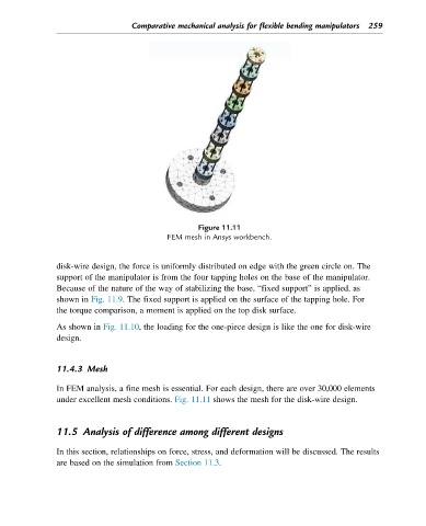
Figure 11.11
FEM mesh in Ansys workbench.
disk-wire design, the force is uniformly distributed on edge with the green circle on. The
support of the manipulator is from the four tapping holes on the base of the manipulator.
Because of the nature of the way of stabilizing the base, “fixed support” is applied, as
shown in Fig. 11.9. The fixed support is applied on the surface of the tapping hole. For
the torque comparison, a moment is applied on the top disk surface.
As shown in Fig. 11.10, the loading for the one-piece design is like the one for disk-wire
design.
11.4.3 Mesh
In FEM analysis, a fine mesh is essential. For each design, there are over 30,000 elements
under excellent mesh conditions. Fig. 11.11 shows the mesh for the disk-wire design.
11.5 Analysis of difference among different designs
In this section, relationships on force, stress, and deformation will be discussed. The results
are based on the simulation from Section 11.3.