
Page 274 - Flexible Robotics in Medicine
P. 274
Comparative mechanical analysis for flexible bending manipulators 263
(Fig. 11.14). From the simulation results shown in Fig. 11.15, we can tell that the shear
stress within the one-piece design is small. Comparing with the study result from the
disk-wire design, the XY plane shear stress is quite small.
Under the same load case and same deformation, we can tell that the shear stress in one-
piece design is a lot smaller than that in the disk-wire design (Fig. 11.16).
11.5.3 Different number of disks in disk-wire design analysis
In disk-wire design, the number of disks and the distance between each disk are set
arbitrarily. The simulation of a different number of disks can tell that this parameter will
affect the force needed to achieve the same deformation. Fig. 11.17 shows the relationship
between the deformation of the top disk and the number of disks. We can say the smaller
the number of disks, the less force needed to control the manipulator. However, there is a
need for enough disks as a guide so that the tendon will not mess up, and they will follow
the relationship in Section 11.3.2.3. Similarly, the larger the distance between two disks is,
the less force is needed to control the manipulator. Both relationships are linear since
2
r $ 0.99. The results are shown in Fig. 11.17.
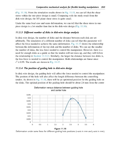
11.5.4 The position of guiding hole in disk-wire design
In disk-wire design, the guiding hole will affect the force needed to control the manipulator.
The position of the hole will also affect the length difference between the controlling
tendon. As shown in Fig. 11.18, there will be an optimized position for the guiding hole on
the disks. The optimal position of the guiding hole should be about 2.6 mm from the center
Figure 11.18
Deformation under same force for different guiding hole positions (x-axis in mm and y-axis in mm).