
Page 340 - Flexible Robotics in Medicine
P. 340
Force sensing in compact concentric tube mechanism with optical fibers 331
For simplification in controlled setups, the temperature has been assumed as a constant.
Therefore the shift in the Bragg wavelength from homogeneous and isotropic strain ðεÞ
alone is given by
Δλ Bragg 5 λ Bragg 1 2 p e Þε;
ð
where p e is the subsumed photo-elastic contribution [18], given by
2
n
p e 5 ½ p 12 2 μðp 11 1 p 12 Þ;
2
where p ij represents the fiber Pockel’s coefficients, and μ is the Poisson’s ratio.
The shift in wavelength makes the FBG highly sensitive to any changes in temperature and
strain with a typical strain sensitivity of 1.15 pm/με and temperature sensitivity of 13 pm/
C [19], making it well suited for procedures requiring high degrees of precision [20].
14.3 Concentric tube robot design
14.3.1 Tube configuration
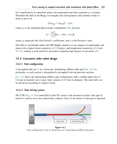
A decoupled tube set [1] in a telescopic dominating stiffness tube pair (Fig. 14.2)is
preferable, as each section is kinematically decoupled from the previous sections.
Fig. 14.2 shows the dominating stiffness pair configuration with a smaller inner tube of
1.6 mm in diameter and a larger outer cannula of 2.5 mm in diameter. The inner tube can
be precurved according to surgical needs.
14.3.2 Tube driving system
The CTR (Fig. 14.3) is controlled by four DC motors with attached encoders. One pair of
motors is used to move the semicircular columns. Each of the motors in this pair is attached
Outer tube Curved inner tube
Figure 14.2
Tube configuration with an illustration of a dominating stiffness tube pair.