
Page 341 - Flexible Robotics in Medicine
P. 341
332 Chapter 14
Figure 14.3
Mechanical transmission model of the concentric tube robot.
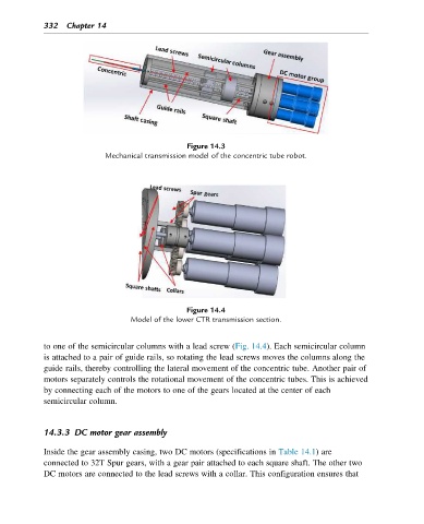
Figure 14.4
Model of the lower CTR transmission section.
to one of the semicircular columns with a lead screw (Fig. 14.4). Each semicircular column
is attached to a pair of guide rails, so rotating the lead screws moves the columns along the
guide rails, thereby controlling the lateral movement of the concentric tube. Another pair of
motors separately controls the rotational movement of the concentric tubes. This is achieved
by connecting each of the motors to one of the gears located at the center of each
semicircular column.
14.3.3 DC motor gear assembly
Inside the gear assembly casing, two DC motors (specifications in Table 14.1) are
connected to 32T Spur gears, with a gear pair attached to each square shaft. The other two
DC motors are connected to the lead screws with a collar. This configuration ensures that