
Page 95 - Flexible Robotics in Medicine
P. 95
80 Chapter 4
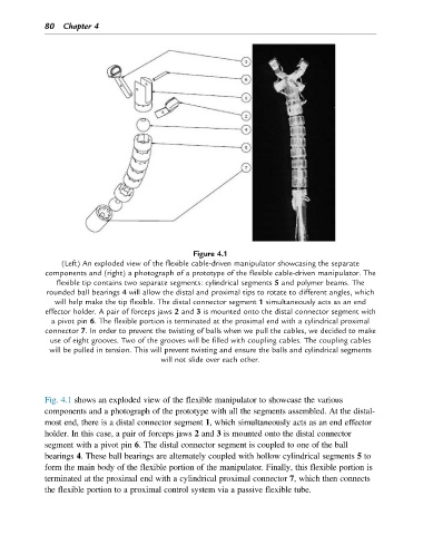
Figure 4.1
(Left) An exploded view of the flexible cable-driven manipulator showcasing the separate
components and (right) a photograph of a prototype of the flexible cable-driven manipulator. The
flexible tip contains two separate segments: cylindrical segments 5 and polymer beams. The
rounded ball bearings 4 will allow the distal and proximal tips to rotate to different angles, which
will help make the tip flexible. The distal connector segment 1 simultaneously acts as an end
effector holder. A pair of forceps jaws 2 and 3 is mounted onto the distal connector segment with
a pivot pin 6. The flexible portion is terminated at the proximal end with a cylindrical proximal
connector 7. In order to prevent the twisting of balls when we pull the cables, we decided to make
use of eight grooves. Two of the grooves will be filled with coupling cables. The coupling cables
will be pulled in tension. This will prevent twisting and ensure the balls and cylindrical segments
will not slide over each other.
Fig. 4.1 shows an exploded view of the flexible manipulator to showcase the various
components and a photograph of the prototype with all the segments assembled. At the distal-
most end, there is a distal connector segment 1, which simultaneously acts as an end effector
holder. In this case, a pair of forceps jaws 2 and 3 is mounted onto the distal connector
segment with a pivot pin 6. The distal connector segment is coupled to one of the ball
bearings 4. These ball bearings are alternately coupled with hollow cylindrical segments 5 to
form the main body of the flexible portion of the manipulator. Finally, this flexible portion is
terminated at the proximal end with a cylindrical proximal connector 7, which then connects
the flexible portion to a proximal control system via a passive flexible tube.