
Page 97 - Flexible Robotics in Medicine
P. 97
82 Chapter 4
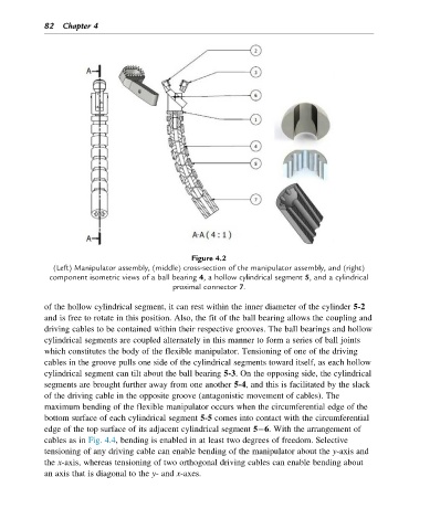
Figure 4.2
(Left) Manipulator assembly, (middle) cross-section of the manipulator assembly, and (right)
component isometric views of a ball bearing 4, a hollow cylindrical segment 5, and a cylindrical
proximal connector 7.
of the hollow cylindrical segment, it can rest within the inner diameter of the cylinder 5-2
and is free to rotate in this position. Also, the fit of the ball bearing allows the coupling and
driving cables to be contained within their respective grooves. The ball bearings and hollow
cylindrical segments are coupled alternately in this manner to form a series of ball joints
which constitutes the body of the flexible manipulator. Tensioning of one of the driving
cables in the groove pulls one side of the cylindrical segments toward itself, as each hollow
cylindrical segment can tilt about the ball bearing 5-3. On the opposing side, the cylindrical
segments are brought further away from one another 5-4, and this is facilitated by the slack
of the driving cable in the opposite groove (antagonistic movement of cables). The
maximum bending of the flexible manipulator occurs when the circumferential edge of the
bottom surface of each cylindrical segment 5-5 comes into contact with the circumferential
edge of the top surface of its adjacent cylindrical segment 5 6. With the arrangement of
cables as in Fig. 4.4, bending is enabled in at least two degrees of freedom. Selective
tensioning of any driving cable can enable bending of the manipulator about the y-axis and
the x-axis, whereas tensioning of two orthogonal driving cables can enable bending about
an axis that is diagonal to the y- and x-axes.