
Page 96 - Flexible Robotics in Medicine
P. 96
Flexible steerable manipulator utilizing complementary configuration 81
The distal tip is composed of two main components, the bending section and the forceps
connector. The bending section consists of cylinders connected to each other via curved
shaped structures. Each cylinder or individual segment has multiple grooves that are
depressions in the inner surface of the cylinder. Each cylinder must be of sufficient thickness
and rigidity to transmit mechanical force and permit segment-to-segment bending. The
grooves are deep enough to allow for the passage of control cables. Control cables are made
of a material with properties that can transmit the desired amount of force and withstand
cyclic loading. One or more grooves will be used to pass control cables that may control
bending or may control the forceps movement. One or more grooves will be used to pass
cables that connect the distal-most segments (forceps connector) to the proximal-most
segment of the distal tip. The distal-most and proximal-most segments of the distal tip may or
may not be identical to the other individual segments, with their purpose being to terminate
the cables holding the distal tip together. The segments of the distal tip are coupled to each
other via a structure with curved surfaces on one or more sides, which may resemble a ball
bearing to allow for movement between the individual segments and the curved surface
structure. The curved surface structure (ball bearing-like or spherical) may have a central
lumen to allow more control cables to pass if desired. The forceps connector is a cylindrical
piece, not unlike the individual segments. There exists a gap in the middle for the forceps to
be housed. A pivot will be housed in this region to allow the forceps to be pivoted upon.
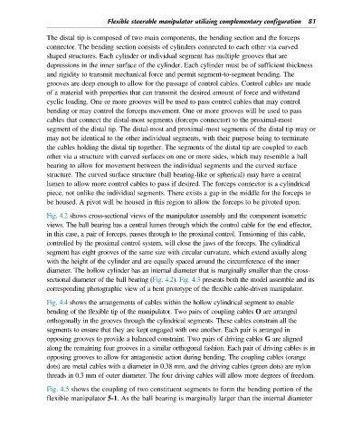
Fig. 4.2 shows cross-sectional views of the manipulator assembly and the component isometric
views. The ball bearing has a central lumen through which the control cable for the end effector,
in this case, a pair of forceps, passes through to the proximal control. Tensioning of this cable,
controlled by the proximal control system, will close the jaws of the forceps. The cylindrical
segment has eight grooves of the same size with circular curvature, which extend axially along
with the height of the cylinder and are equally spaced around the circumference of the inner
diameter. The hollow cylinder has an internal diameter that is marginally smaller than the cross-
sectional diameter of the ball bearing (Fig. 4.2). Fig. 4.3 presents both the model assemble and its
corresponding photographic view of a bent prototype of the flexible cable-driven manipulator.
Fig. 4.4 shows the arrangements of cables within the hollow cylindrical segment to enable
bending of the flexible tip of the manipulator. Two pairs of coupling cables O are arranged
orthogonally in the grooves through the cylindrical segments. These cables constrain all the
segments to ensure that they are kept engaged with one another. Each pair is arranged in
opposing grooves to provide a balanced constraint. Two pairs of driving cables G are aligned
along the remaining four grooves in a similar orthogonal fashion. Each pair of driving cables is in
opposing grooves to allow for antagonistic action during bending. The coupling cables (orange
dots) are metal cables with a diameter in 0.38 mm, and the driving cables (green dots) are nylon
threads in 0.3 mm of outer diameter. The four driving cables will allow more degrees of freedom.
Fig. 4.5 shows the coupling of two constituent segments to form the bending portion of the
flexible manipulator 5-1. As the ball bearing is marginally larger than the internal diameter