
Page 99 - Flexible Robotics in Medicine
P. 99
84 Chapter 4
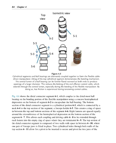
Figure 4.5
Cylindrical segments and ball bearings are alternately coupled together to form the flexible cable-
driven manipulator; tilting of the top cylindrical segment demonstrates the bending mechanism.
The central lumen of a ball bearing can be further flared outward at both ends to produce
openings of a larger diameter. This reduces the kinking of the end effector control cable, which
extends through the central lumen, especially during the bending of the flexible manipulator. By
doing so, less friction is experienced during tensioning control cables.
Fig. 4.6 shows the distal connector segment 6-1, which couples to the distal-most ball
bearing on the bending portion of the flexible manipulator using a concave hemispherical
depression on the bottom of segment 6-2 to encapsulate the ball bearing. The bottom
section of the distal connector segment is a cylindrical portion 6-3, which is connected by a
neck 6-4 to the top section of the segment, a forceps holder 6-5. This creates a ring of space
in between the top and bottom sections of the segment 6-6. Eight lumens are spaced equally
around the circumference of the hemispherical depression on the bottom section of the
segment 6 7. This allows each coupling and driving cable 6 8 to be extended through
each lumen into the empty ring of space where they are terminated 6 9. The top section of
the distal connector segment is composed of two walls with space in between 6 10, where
one pair of forceps jaws is fitted in place. Two cylindrical holes through both walls of the
top section 6 11 allow for a pivot to be inserted to secure and pivot the two jaws of the