Page 114 - Fluid Mechanics and Thermodynamics of Turbomachinery
P. 114

Axial-flow Turbines: Two-dimensional Theory  95
                          hence,

                                        1
                              .h 2  h 3 / C .c y2 C c y3 /[.c y2  U/  .c y3 C U/] D 0.
                                        2
                          It is observed from the velocity triangles of Figure 4.1 that c y2  U D w y2 ,c y3 C
                          U D w y3 and c y2 C c y3 D w y2 C w y3 . Thus,

                                                 2
                                        1
                              .h 2  h 3 / C .w 2  w / D 0.
                                        2  y2    y3
                                         1 2
                          Add and subtract c to the above equation
                                         2 x
                                   1  2      1  2
                              h 2 C w D h 3 C w or h 02rel D h 03rel.                      (4.4)
                                     2
                                               3
                                   2         2
                                                                                       2
                                                                                     1
                          Thus, we have proved that the relative stagnation enthalpy, h 0rel D h C w , remains
                                                                                     2
                          unchanged through the rotor of an axial turbomachine. It is implicitly assumed that
                          no radial shift of the streamlines occurs in this flow. In a radial flow machine a
                          more general analysis is necessary (see Chapter 7) which takes account of the blade
                          speed change between rotor inlet and outlet.
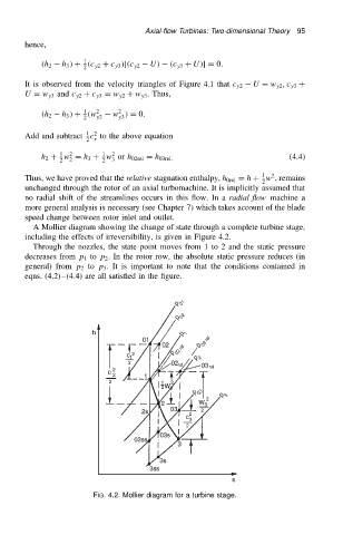
                            A Mollier diagram showing the change of state through a complete turbine stage,
                          including the effects of irreversibility, is given in Figure 4.2.
                            Through the nozzles, the state point moves from 1 to 2 and the static pressure
                          decreases from p 1 to p 2 . In the rotor row, the absolute static pressure reduces (in
                          general) from p 2 to p 3 . It is important to note that the conditions contained in
                          eqns. (4.2) (4.4) are all satisfied in the figure.


                                           FIG. 4.2. Mollier diagram for a turbine stage.
   109   110   111   112   113   114   115   116   117   118   119