
Page 183 - Fluid Mechanics and Thermodynamics of Turbomachinery
P. 183
164 Fluid Mechanics, Thermodynamics of Turbomachinery
Combining eqns. (5.35), (5.36) and (5.39) in eqn. (5.37), then
/ c y1 /.2U/. (5.40a)
b D .c x /U/ tan.ˇ m
The foregoing exercise can be repeated for the second type of fan having outlet
straightening vanes and, assuming frictionless flow through the “straighteners”, the
rotor blade element efficiency becomes,
/ C c y2 /.2U/. (5.40b)
b D .c x /U/ tan.ˇ m
Some justification for ignoring the losses occurring in the guide vanes is found
by observing that the ratio of guide vane pressure change to rotor pressure rise is
normally small in ventilating fans. For example, in the first type of fan
1
2
p 1 / + . c //. Uc y1 / D c y1 /2.U/,
.p e p 1 //.p 2 y1
2
the tangential velocity c y1 being rather small compared with the blade speed U.
Lift coefficient of a fan aerofoil
For a specified blade element geometry, blade speed and lift/drag ratio the temper-
ature and pressure rises can be determined if the lift coefficient is known. An
estimate of lift coefficient is most easily obtained from two-dimensional aerofoil
potential flow theory. Glauert (1959) shows for isolated aerofoils of small camber
and thickness, that
C L D 2 sin , (5.41)
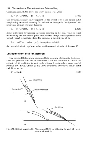
FIG. 5.18. Method suggested by Wislicenus (1947) for obtaining the zero lift line of
cambered aerofoils.