
Page 181 - Fluid Mechanics and Thermodynamics of Turbomachinery
P. 181
162 Fluid Mechanics, Thermodynamics of Turbomachinery
lift force of a single isolated blade. As a guide to the degree of this interference,
the exact solution obtained by Weinig (1935) and used by Wislicenus (1947) for
a row of thin flat plates is of value and is shown in Figure 5.16. This illustrates
the dependence of k on space chord ratio for several stagger angles. The rather
pronounced effect of stagger for moderate space chord ratios should be noted as
well as the asymptotic convergence of k towards unity for higher space chord ratios.
Two simple types of axial-flow fan are shown in Figure 5.17 in which the inlet
and outlet flows are entirely axial. In the first type (a), a set of guide vanes provide a
contra-swirl and the flow is restored to the axial direction by the rotor. In the second
type (b), the rotor imparts swirl in the direction of blade motion and the flow is
restored to the axial direction by the action of outlet straighteners (or outlet guide
vanes). The theory and design of both the above types of fan have been investigated
by Van Niekerk (1958) who was able to formulate expressions for calculating the
optimum sizes and fan speeds using blade element theory.
Blade element theory
A blade element at a given radius can be defined as an aerofoil of vanishingly
small span. In fan-design theory it is commonly assumed that each such element
operates as a two-dimensional aerofoil, behaving completely independently of condi-
tions at any other radius. Now the forces impressed upon the fluid by unit span of
a single stationary blade have been considered in some detail already, in Chapter 3.
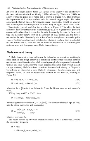
Considering an element of a rotor blade dr, at radius r, the elementary axial and
tangential forces, dX and dY respectively, exerted on the fluid are, referring to
Figure 3.5,
D cos ˇ m /dr, .5.30/
dX D .L sin ˇ m
dY D .L cos ˇ m C D sin ˇ m /dr, .5.31/
1
where tan ˇ m D ftan ˇ 1 C tan ˇ 2 g and L, D are the lift and drag on unit span of a
2
blade.
Writing tan
D D/L D C D /C L then,
tan
cos ˇ m /dr.
dX D L.sin ˇ m
2
1
Introducing the lift coefficient C L D L/. w l/ for the rotor blade (cf. eqn. (3.16a))
2 m
into the above expression and rearranging,
2
c lC L dr sin.ˇ m
/
x
dX D Ð , (5.32)
2
2 cos ˇ m cos
where c x D w m cos ˇ m .
The torque exerted by one blade element at radius r is rd Y. If there are Z blades
the elementary torque is
d D rZdY
D rZL.cos ˇ m C tan
sin ˇ m /dr,