
Page 128 - Fluid Power Engineering
P. 128
102 Cha pte r F o u r
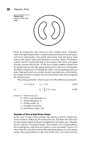
FIGURE 4.13
Layout of the port
plate.
block, to reciprocate with respect to this cylinder block. Therefore,
each of the pistons performs a reciprocating motion between its upper
and lower dead points. The piston movement from the lower dead
point to the upper dead point produces a suction stroke. The fluid is
sucked via the control opening on the suction side of the port plate
into the cylinder block bore. As the drive shaft is further rotated and
the piston moves from the upper dead point to the lower dead point,
the fluid is displaced out through the other control opening (pressure
side). During the delivery stroke, the driving shaft acts on the disk by
the torque needed to produce the forces that drive the pistons against
the load pressure.
The pump geometric volume is given by the following expression:
h = D sin α, V = z A h (4.23)
g
π
2
or V = d Dz sin α (4.24)
g 4
where A = Piston area, m 2
D = Pitch circle diameter, m
d = Piston diameter, m
h = Piston stroke, m
z = Number of pistons
α = Inclination angle, rad
Pulsation of Flow of Axial Piston Pumps
In the case of axial piston pumps, the pistons perform simple har-
monic motions, following the sinusoidal law. The flow rate delivered
by each piston equals its speed multiplied by the piston area. Neglect-
ing the effects of internal leakage, fluid inertia, and compressibility,
the resulting flow rate from each piston is also sinusoidal. Figure 4.14
shows the flow rate delivered by the individual pistons of a five-piston
pump. The pump delivery is the sum of the flow rates delivered by