
Page 126 - Fluid Power Engineering
P. 126
100 Cha pte r F o u r
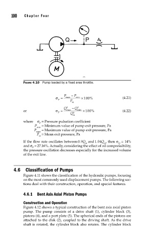
FIGURE 4.10 Pump loaded by a fixed area throttle.
P − P
σ = max min × 100 % (4.21)
P P
m
Q 2 − Q 2
or σ = max min × 100 % (4.22)
P 2
Q
m
where σ = Pressure pulsation coefficient
P
P = Minimum value of pump exit pressure, Pa
min
P = Maximum value of pump exit pressure, Pa
max
P = Mean exit pressure, Pa
m
If the flow rate oscillates between 09. Q and 104. Q , then σ = 14%
m m Q
and σ = 27.16%. Actually, considering the effect of oil compressibility,
P
the pressure oscillation decreases especially for the increased volume
of the exit line.
4.6 Classification of Pumps
Figure 4.11 shows the classification of the hydraulic pumps, focusing
on the most commonly used displacement pumps. The following sec-
tions deal with their construction, operation, and special features.
4.6.1 Bent Axis Axial Piston Pumps
Construction and Operation
Figure 4.12 shows a typical construction of the bent axis axial piston
pump. The pump consists of a drive shaft (1), cylinder block (3),
pistons (4), and a port plate (5). The spherical ends of the pistons are
attached to the disk (2), coupled to the driving shaft. As the drive
shaft is rotated, the cylinder block also rotates. The cylinder block