
Page 129 - Fluid Power Engineering
P. 129
Hydraulic Pumps 103
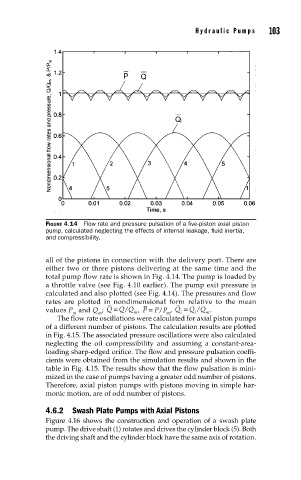
FIGURE 4.14 Flow rate and pressure pulsation of a fi ve-piston axial piston
pump, calculated neglecting the effects of internal leakage, fl uid inertia,
and compressibility.
all of the pistons in connection with the delivery port. There are
either two or three pistons delivering at the same time and the
total pump flow rate is shown in Fig. 4.14. The pump is loaded by
a throttle valve (see Fig. 4.10 earlier). The pump exit pressure is
calculated and also plotted (see Fig. 4.14). The pressures and flow
rates are plotted in nondimensional form relative to the mean
values P and Q ; Q = Q Q , P = P P , Q = Q Q .
/
/
/
m m m m i i m
The flow rate oscillations were calculated for axial piston pumps
of a different number of pistons. The calculation results are plotted
in Fig. 4.15. The associated pressure oscillations were also calculated
neglecting the oil compressibility and assuming a constant-area-
loading sharp-edged orifice. The flow and pressure pulsation coeffi-
cients were obtained from the simulation results and shown in the
table in Fig. 4.15. The results show that the flow pulsation is mini-
mized in the case of pumps having a greater odd number of pistons.
Therefore, axial piston pumps with pistons moving in simple har-
monic motion, are of odd number of pistons.
4.6.2 Swash Plate Pumps with Axial Pistons
Figure 4.16 shows the construction and operation of a swash plate
pump. The drive shaft (1) rotates and drives the cylinder block (5). Both
the driving shaft and the cylinder block have the same axis of rotation.