
Page 122 - Fluid Power Engineering
P. 122
96 Cha pte r F o u r
The mechanical power ω(T − T F ) is converted into equal hydraulic
power, QP , then
tC
η = η η η (4.11)
T v m h
In the steady-state operation, the real displacement pump is
described by the following relations:
Q = V nη v (4.12)
g
Δ= 2π
N = N η or QP nTη (4.13)
h m T T
V g
Then T = Δ P (4.14)
2πη η
m h
where N = Hydraulic power, W
h
N = Mechanical power, W
m
ΔP = Difference between the pump output and input
pressures, ΔP = P − P , Pa
i
If the pump input pressure, P , is too small compared with the
i
delivery pressure, P, then it may be neglected, and the pressure dif-
ference, ΔP, equals the pump exit pressure, P. If so, then
V g
T = P (4.15)
2πη η
m h
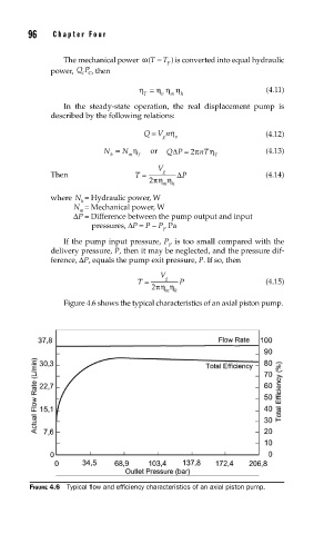
Figure 4.6 shows the typical characteristics of an axial piston pump.
FIGURE 4.6 Typical fl ow and effi ciency characteristics of an axial piston pump.