
Page 117 - Fluid Power Engineering
P. 117
Hydraulic Pumps 91
4.2 Ideal Pump Analysis
The pump displacement is defined as the volume of liquid delivered
by the pump per revolution, assuming no leakage and neglecting
the effect of oil compressibility. It depends on the maximum and
minimum values of the pumping chamber volume, the number of
pumping chambers, and the number of pumping strokes per one
revolution of the driving shaft. This volume depends on the pump
geometry; therefore, it is also called the geometric volume, V . It is
g
given by the following equation:
V = ( V − V ) zi (4.1)
g max min
where i = Number of pumping strokes per revolution
3
V = Pump displacement (geometric volume), m /rev
g
V = Maximum chamber volume, m 3
max
V = Minimum chamber volume, m 3
min
z = Number of pumping chambers
Assuming an ideal pump, with no internal leakage, no friction,
and no pressure losses, the pump flow rate is given by the following
expression:
Q = V n (4.2)
g
t
3
where Q = Pump theoretical flow rate, m /s
t
n = Pump speed, rev/s
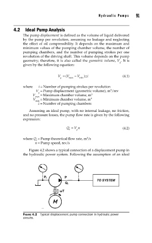
Figure 4.2 shows a typical connection of a displacement pump in
the hydraulic power system. Following the assumption of an ideal
FIGURE 4.2 Typical displacement pump connection in hydraulic power
circuits.