
Page 118 - Fluid Power Engineering
P. 118
92 Cha pte r F o u r
pump, the input mechanical power is equal to the increase in the fluid
power as shown by the following equation:
Δ
2π nT = Q P P =( − ) V n p (4.3)
t t i g
V g
or T = 2π Δ P (4.4)
t
where T = Pump theoretical driving torque, Nm
t
Δ P = Pressure increase due to pump action, Pa
3
Example 4.1 A gear pump of 12.5 cm geometric volume operated at 1800 rev/min
delivers the oil at 16 MPa pressure. Assuming an ideal pump, calculate the pump
flow rate, Q , the increase in the oil power, ΔN, the hydraulic power at the pump
t
exit line, N , and the driving torque, T , if the inlet pressure is 200 kPa.
out
t
×
Q = V n = 12 5 10 −6 × 1800 = 375 10 −4 m / s = 225 . liiters/min
×
3
.
.
t g 60
V 12 5 . × 10 −6
T = g Δ P = ( 16 × 10 6 − × 10 ) = 31 4 Nm
5 5
2
.
t 2π 2π
×
×
×
6
ΔN = Q ΔP = 37 510 − 5 × ( 1610 − 2 10 ) = 55925 W
.
5
t
×
×
6
N = Q P = 37 5 10 − 5 × 16 10 = 6000 W
.
out t
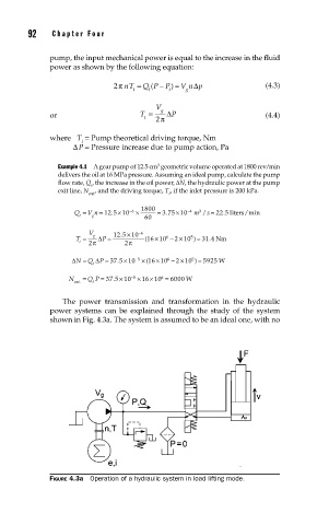
The power transmission and transformation in the hydraulic
power systems can be explained through the study of the system
shown in Fig. 4.3a. The system is assumed to be an ideal one, with no
FIGURE 4.3a Operation of a hydraulic system in load lifting mode.