
Page 119 - Fluid Power Engineering
P. 119
Hydraulic Pumps 93
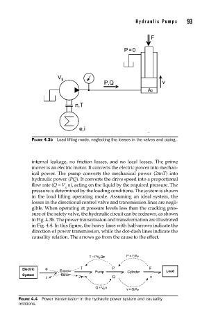
FIGURE 4.3b Load lifting mode, neglecting the losses in the valves and piping.
internal leakage, no friction losses, and no local losses. The prime
mover is an electric motor. It converts the electric power into mechan-
ical power. The pump converts the mechanical power (2πnT) into
hydraulic power (PQ). It converts the drive speed into a proportional
flow rate (Q = V n), acting on the liquid by the required pressure. The
g
pressure is determined by the loading conditions. The system is shown
in the load lifting operating mode. Assuming an ideal system, the
losses in the directional control valve and transmission lines are negli-
gible. When operating at pressure levels less than the cracking pres-
sure of the safety valve, the hydraulic circuit can be redrawn, as shown
in Fig. 4.3b. The power transmission and transformation are illustrated
in Fig. 4.4. In this figure, the heavy lines with half-arrows indicate the
direction of power transmission, while the dot-dash lines indicate the
causality relation. The arrows go from the cause to the effect.
FIGURE 4.4 Power transmission in the hydraulic power system and causality
relations.