
Page 49 - Fluid Power Engineering
P. 49
26 Cha pte r T w o
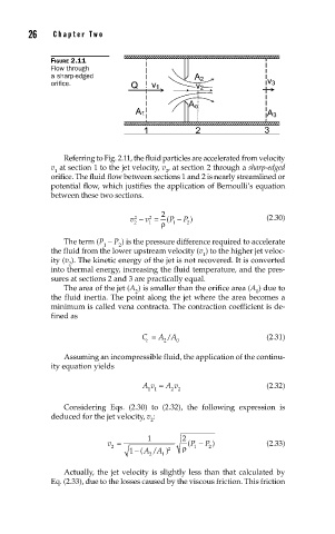
FIGURE 2.11
Flow through
a sharp-edged
orifi ce.
Referring to Fig. 2.11, the fluid particles are accelerated from velocity
v at section 1 to the jet velocity, v , at section 2 through a sharp-edged
1 2
orifice. The fluid flow between sections 1 and 2 is nearly streamlined or
potential flow, which justifies the application of Bernoulli’s equation
between these two sections.
2
v − v = ( P − P ) (2.30)
2
2
2 1 ρ 1 2
The term (P − P ) is the pressure difference required to accelerate
1 2
the fluid from the lower upstream velocity (v ) to the higher jet veloc-
1
ity (v ). The kinetic energy of the jet is not recovered. It is converted
2
into thermal energy, increasing the fluid temperature, and the pres-
sures at sections 2 and 3 are practically equal.
The area of the jet (A ) is smaller than the orifice area (A ) due to
2 0
the fluid inertia. The point along the jet where the area becomes a
minimum is called vena contracta. The contraction coefficient is de-
fined as
C = A A (2.31)
/
c 2 0
Assuming an incompressible fluid, the application of the continu-
ity equation yields
Av = A v (2.32)
11 2 2
Considering Eqs. (2.30) to (2.32), the following expression is
deduced for the jet velocity, v :
2
1 2
v = ( P − P ) (2.33)
2 2 ρ 1 2
1 − ( AA )
/
2 1
Actually, the jet velocity is slightly less than that calculated by
Eq. (2.33), due to the losses caused by the viscous friction. This friction