
Page 51 - Fluid Power Engineering
P. 51
28 Cha pte r T w o
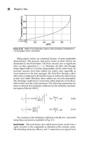
FIGURE 2.12 Effect of the diameter’s ratio on the contraction coeffi cient of
a sharp-edged orifi ce, calculated.
Sharp-edged orifices are preferred because of their predictable
characteristics. The pressure and power losses in these orifices are
dominated by the fluid inertia. The fluid viscosity has no significant
effect on their operation (C ≈ 1). Therefore, the flow rate through
v
sharp-edged orifices is viscosity-independent. On the other hand, for
economy reasons, short tube orifices are widely used, especially as
fixed restrictors in the flow passages. The fluid flow through a short
tube orifice is subjected to the friction losses as well as the minor losses
at inlet and outlet. Therefore, these orifices are viscosity- dependent.
The discharge coefficient of a short tube orifice depends on the Reyn-
olds number and the orifice geometry. The following expressions are
used to calculate the discharge coefficient for the turbulent and lami-
nar regions [Merritt (1967)]:
⎡ 1 ⎤ − 1 2
⎢ ⎛ L ⎞ ⎥ Red
2
+
.
.
C = 1 5 13 74 ⎜ ⎟ ⎥ For > 50 (2.40)
d ⎢ ⎝ Re d⎠ L
⎢ ⎣ ⎥ ⎦
1
⎡ 64 L⎤ − 2
.
C = 228 + ⎥ For Red (2.41)
⎢
d < 50
⎣ Re d ⎦ L
The variation of the discharge coefficient with (Re d/L), calculated
using these expressions, is plotted in Fig. 2.13.
Local Losses The local losses, also called minor losses, result from a
rapid variation in the magnitude or direction of the velocity vector.
The throttling elements, elbows, and T connections are typical local