
Page 52 - Fluid Power Engineering
P. 52
Hydraulic Oils and Theor etical Backgr ound 29
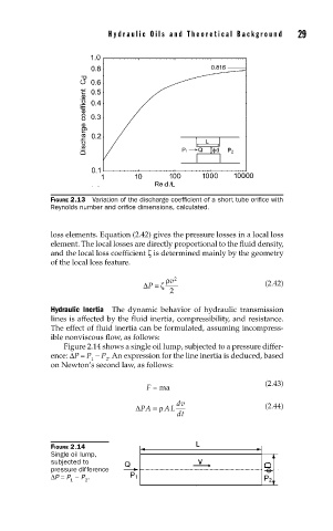
FIGURE 2.13 Variation of the discharge coeffi cient of a short tube orifi ce with
Reynolds number and orifi ce dimensions, calculated.
loss elements. Equation (2.42) gives the pressure losses in a local loss
element. The local losses are directly proportional to the fluid density,
and the local loss coefficient ζ is determined mainly by the geometry
of the local loss feature.
ρ v 2
ΔP =ζ (2.42)
2
Hydraulic Inertia The dynamic behavior of hydraulic transmission
lines is affected by the fluid inertia, compressibility, and resistance.
The effect of fluid inertia can be formulated, assuming incompress-
ible nonviscous flow, as follows:
Figure 2.14 shows a single oil lump, subjected to a pressure differ-
ence: ΔP = P − P . An expression for the line inertia is deduced, based
1 2
on Newton’s second law, as follows:
(2.43)
F = ma
dv
ΔPA =ρ AL (2.44)
dt
FIGURE 2.14
Single oil lump,
subjected to
pressure difference
ΔP = P − P .
1 2