
Page 151 - Fluid-Structure Interactions Slender Structure and Axial Flow (Volume 1)
P. 151
PIPES CONVEYING FLUID: LINEAR DYNAMICS I 133
3.5.6 Experiments
The first set of experiments were conducted with horizontal cantilevers conveying air,
water or oil, with rubber pipes, in some cases fitted with end-nozzles, and metal pipes
(Pai‘doussis 1963; Gregory & PaYdoussis 1966b). The apparatus for the experiments with
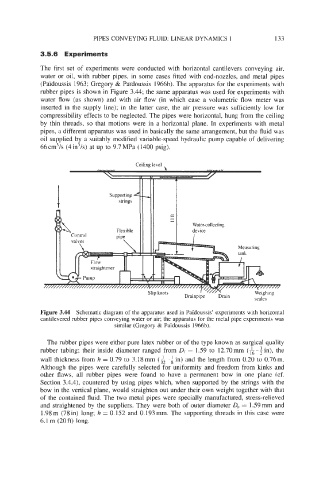
rubber pipes is shown in Figure 3.44; the same apparatus was used for experiments with
water flow (as shown) and with air flow (in which case a volumetric flow meter was
inserted in the supply line): in the latter case, the air pressure was sufficiently low for
compressibility effects to be neglected. The pipes were horizontal, hung from the ceiling
by thin threads, so that motions were in a horizontal plane. In experiments with metal
pipes, a different apparatus was used in basically the same arrangement, but the fluid was
oil supplied by a suitably modified variable-speed hydraulic pump capable of delivering
66cm’/s (4in’/s) at up to 9.7MPa (1400 psig).
Ceiling level
u:
. ”’ b
Supporting
strings
Water-collecting
device
I
Measuring
m
n.. 1 .
allp KIlOIS
Drainpipe Drain
scales
Figure 3.44 Schematic diagram of the apparatus used in Paldoussis’ experiments with horizontal
cantilevered rubber pipes conveying water or air; the apparatus for the metal pipe experiments was
similar (Gregory & Pai’doussis 1966b).
The rubber pipes were either pure latex rubber or of the type known as surgical quality
rubber tubing; their inside diameter ranged from Di = 1.59 to 12.70mm (k- in), the
wall thickness from h = 0.79 to 3.18 mm (& - $ in) and the length from 0.20 to 0.76 m.
Although the pipes were carefully selected for uniformity and freedom from kinks and
other flaws, all rubber pipes were found to have a permanent bow in one plane (cf.
Section 3.4.4), countered by using pipes which, when supported by the strings with the
bow in the vertical plane, would straighten out under their own weight together with that
of the contained fluid. The two metal pipes were specially manufactured, stress-relieved
and straightened by the suppliers. They were both of outer diameter Do = 1.59 mm and
1.98 m (78 in) long; h = 0.152 and 0.193 mm. The supporting threads in this case were
6.1 m (20 ft) long.