
Page 155 - Fluid-Structure Interactions Slender Structure and Axial Flow (Volume 1)
P. 155
PIPES CONVEYING FLUID: LINEAR DYNAMICS I 137
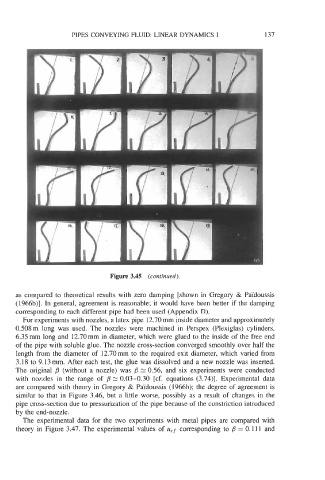
Figure 3.45 (continued).
as compared to theoretical results with zero damping [shown in Gregory & Paldoussis
(1966b)l. In general, agreement is reasonable; it would have been better if the damping
corresponding to each different pipe had been used (Appendix D).
For experiments with nozzles, a latex pipe 12.70 mm inside diameter and approximately
0.508 m long was used. The nozzles were machined in Perspex (Plexiglas) cylinders,
6.35 mm long and 12.70 mm in diameter, which were glued to the inside of the free end
of the pipe with soluble glue. The nozzle cross-section converged smoothly over half the
length from the diameter of 12.70mm to the required exit diameter, which varied from
3.18 to 9.13 mm. After each test, the glue was dissolved and a new nozzle was inserted.
The original /3 (without a nozzle) was p = 0.56, and six experiments were conducted
with nozzles in the range of p 0.03-0.30 [cf. equations (3.74)]. Experimental data
are compared with theory in Gregory & Paldoussis (1966b); the degree of agreement is
similar to that in Figure 3.46, but a little worse, possibly as a result of changes in the
pipe cross-section due to pressurization of the pipe because of the constriction introduced
by the end-nozzle.
The experimental data for the two experiments with metal pipes are compared with
theory in Figure 3.47. The experimental values of ucf corresponding to /3 = 0.11 1 and