
Page 199 - Fluid-Structure Interactions Slender Structure and Axial Flow (Volume 1)
P. 199
PIPES CONVEYING FLUID: LINEAR DYNAMICS I 181
-
EI El
j- I / j / j+ I
I
L/+i------4
I I I I I 1 I
4L 3
First Second -
3 - Stop propagation propagation
-band band Stopband band Stopband -
t-c- --e----4.
-
1
I
- \ '--/ \
I
3 0 / 7 / '------'
+
2 -I-/
4 1 I I I I I I
3 =- T -
\ -
2- '\
\ -
\
1- \ Positive-going wave
\ Negative-going wave -
'--4
\ -
\
\
\,,,,,, -
4: I I I I I I I
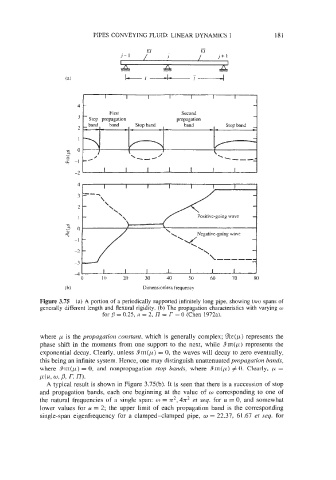
where p is the propagation constant, which is generally complex; %e(p) represents the
phase shift in the moments from one support to the next, while 9rn(p) represents the
exponential decay. Clearly, unless 4im(p) = 0, the waves will decay to zero eventually,
this being an infinite system. Hence, one may distinguish unattenuated propagation bands,
where .9m(p) = 0, and nonpropagation stop bands, where Sm(p) # 0. Clearly, p =
F(K w, P, r. m.
A typical result is shown in Figure 3.75(b). It is seen that there is a succession of stop
and propagation bands, each one beginning at the value of o corresponding to one of
the natural frequencies of a single span: o = n2, 4n2 et seq. for u = 0, and somewhat
lower values for u = 2; the upper limit of each propagation band is the corresponding
single-span eigenfrequency for a clamped-clamped pipe, w = 22.37, 61.67 et seq. for