
Page 200 - Fluid-Structure Interactions Slender Structure and Axial Flow (Volume 1)
P. 200
182 SLENDER STRUCTURES AND AXIAL FLOW
u = 0, and a little lower for u = 2, for reasons to become evident two paragraphs hence.
The propagation bands become wider with increasing u and, as the divergence limit is
approached, u = n, the first propagation band reaches w + 0. Also, from the %e(p)
curves it is obvious that positively and negatively travelling waves have different phases
and hence phase velocities, which again shows that the system does not possess classical
normal modes (Section 3.7.1).
The case of a finite N follows the same pattern. One eventually obtains an N x N
matrix equation giving N discrete frequencies for each propagation band, rather than a
continuum. Thus, in the case of a pipe with p = 0.25, u = I7 = r = 0 and N = 8, one
obtains eight eigenfrequencies: n2 5 w 5 21.67 (< 22.37) in the first band, and another
eight 4n2 I o 5 60.52 (< 61.67) in the second band.
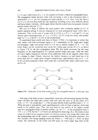
To understand these results and those in Figure 3.75(b), it is important to realize that
only modes with half-wavelength equal to or a submultiple of the single-span length
can propagate: eight such modes when N = 8, and an infinite number for N + 00. The
mode shapes can be visualized most easily for a three-span system (N = 3), as shown
in Figure 3.76 for the first propagation band. The first mode obviously has the same
frequency as the eigenfrequency of a pinned-pinned single-span pipe, while the other
two have higher frequencies because of the additional strain at the supports where there
is a change in slope. Clearly, however, the highest frequency in each band has to be
lower than that of a single-span clamped-clamped pipe, approaching it only as N + 00.
In the second propagation band, each mode has a second-mode shape within each span,
and so on.
Figure 3.76 Schematics of the three modes in the first propagation band for a three-span pipe
(N = 3).
If the pipe of the finite system is nonuniform, some new and interesting features develop.
Chen considers the eight-span system with each span the same as all the others (p =
0.25, u = I7 = 0), except that f = 0 for all spans but the fourth and fifth where r = -4.
When the pipe is nonuniform, some eigenfrequencies exist in what would have been stop
bands in the uniform pipe. Thus, the stop band of one portion of the piping system
may be a propagation band in another portion; e.g. for f = -4, the propagation band is
7.51 5 w 5 9.91, but for f = 0 waves are attenuated in that range of w. The modes in that
range are called energy-trapping modes, for obvious reasons: any energy that comes into
the unattenuating part of the system is accumulated there, but dissipated elsewhere. For
this example, two energy-trapping modes are found: w = 9.00 and w = 38.81. In these
modes, the amplitudes of the fourth and fifth spans are much larger than those of the