
Page 287 - Fluid-Structure Interactions Slender Structure and Axial Flow (Volume 1)
P. 287
268 SLENDER STRUCTURES AND AXIAL FLOW
the text, e.g. in connection with the stability of long pipelines on elastic foundations in
Section 3.7.
The most enduring benefit of this research, however, is in developing the fundamentals
and methods which are used in related topics involving axial-flow -structure interactions,
which do have engineering applications. For example, the dynamics of cylindrical bodies
in axial or annular flow and the dynamics of shells containing or immersed in axial flow,
covered in Volume 2, can be understood in simple terns, modelled mathematically and
solved by means of the work presented throughout Volume 1.
4.7.1 The Coriolis mass-flow meter
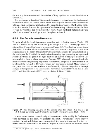
The principle of the Coriolis/gyroscopic mass-flow meter is familiar to most (Plache 1979;
Smith & Ruesch 1991): the whole flow goes through a U- or Q-shaped pipe which is
attached to a T-shaped leaf-spring, as shown in Figure 4.37. Together they form a tuning
fork which is excited electromagnetically close to its resonant frequency in the plane
perpendicular to the paper. The resultant vibration (rotation vector S2) subjects the fluid in
the two legs of the U to Coriolis acceleration of opposing sign, generating a torque which
periodically twists the pipe at the right-hand end in and out of the paper as shown. The
twist angle 0 is linearly related to the mass flow rate MU; it is usually measured optically,
since deflections are generally very small. Alternatively, the phase of the vibration in the
two legs of the U, which is 180" out of phase, may be measured instead. Many variants of
the system described are now available, manufactured by different companies. A thorough
analysis of the operation of the Coriolis mass-flow meter is provided by Raszillier & Durst
(1991) and Raszillier et al. (1993); see also Sultan & Hemp (1989).
. . . . . . .
End view
Figure 4.37 The operating principle of the Coriolis mass-flow meter. A, U-shaped pipe;
B, T-shaped leaf spring; C, electromagnetic exciter; D, optical sensors; see Plache (1979).
It is not known to what extent the original invention was influenced by the fundamental
work described in this book, but probably not much.? Nevertheless, when improve-
ments to the original designs were contemplated, the manufacturers turned to the very
researchers who contributed to the work in Chapters 3,4 and 6 for consultation and further
+The first U.S. patent for a Coriolis-effect meter was issued in 1947.