
Page 289 - Fluid-Structure Interactions Slender Structure and Axial Flow (Volume 1)
P. 289
270 SLENDER STRUCTURES AND AXIAL FLOW
~
1 2 3 4 5 6 7 8 9 10 11 12
(a)
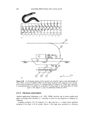
Figure 4.38 (a) Swimming motions of the common eel, Anguilla vulgaris, from photographs by
Gray (1968), as given in Lighthill (1969). (b) Schematic elevation of the catamaran used to demon-
strate ichthyoid propulsion, showing: A, overhead electrical conductor; B, ‘trolley-type’ conductor;
C, motor-pump unit; D, catamaran; E, pump inlet; F, pump outlet; G, thin brass plate; H, Tygon
pipes; I, flow adaptor; J, clips for attachment (PaYdoussis 1976).
4.7.3 Vibration attenuation
Another application (Sugiyama et ul. 1992, 1996b) involves one or more cantilevered
pipes conveying fluid attached to a vibrating structure for the purposes of dumping its
vibration.
Looking at Figure 3.27, for instance, it is clear that for u = 4 there exists optimum
damping of the pipe in all its modes. Hence, if this pipe were attached to a vibrating