
Page 342 - Fluid-Structure Interactions Slender Structure and Axial Flow (Volume 1)
P. 342
322 SLENDER STRUCTURES AND AXIAL FLOW
I
I
i
I
I
I
‘Snap’
\
I
I
I
I
Load I I I
I
I
I-! e 1: I I I I l l c
-
I
0
15 20 25
MUZl/k
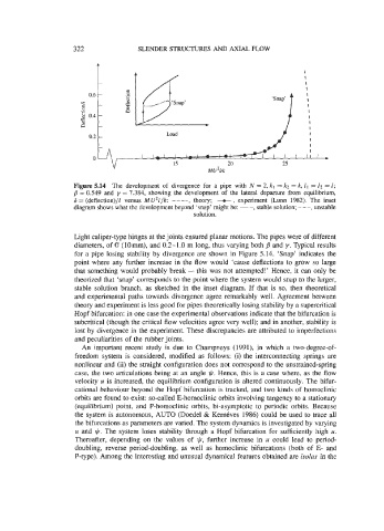
Figure 5.14 The development of divergence for a pipe with N = 2, kl = k2 = k, 11 = 12 = 1;
B = 0.549 and y = 7.384, showing the development of the lateral departure from equilibrium,
6 = (deflection)/l versus MU21/k: ----, theory; e, experiment (Lunn 1982). The inset
diagram shows what the development beyond ‘snap’ might be: -, stable solution; - - -, unstable
solution.
Light caliper-type hinges at the joints ensured planar motions. The pipes were of hfferent
diameters, of 0 (lorn), and 0.2-1.0 m long, thus varying both B and y. Typical results
for a pipe losing stability by divergence are shown in Figure 5.14. ‘Snap’ indicates the
point where any further increase in the flow would ‘cause deflections to grow so large
that something would probably break - this was not attempted!’ Hence, it can only be
theorized that ‘snap’ corresponds to the point where the system would snap to the larger,
stable solution branch, as sketched in the inset diagram. If that is so, then theoretical
and experimental paths towards divergence agree remarkably well. Agreement between
theory and experiment is less good for pipes theoretically losing stability by a supercritical
Hopf bifurcation: in one case the experimental observations indicate that the bifurcation is
subcritical (though the critical flow velocities agree very well); and in another, stability is
lost by divergence in the experiment. These discrepancies are attributed to imperfections
and peculiarities of the rubber joints.
An important recent study is due to Champneys (1991), in which a two-degree-of-
freedom system is considered, modified as follows: (i) the interconnecting springs are
nonlinear and (ii) the straight configuration does not correspond to the unstrained-spring
case, the two articulations being at an angle @. Hence, this is a case where, as the flow
velocity u is increased, the equilibrium configuration is altered continuously. The bifur-
cational behaviour beyond the Hopf bifurcation is tracked, and two kinds of homoclinic
orbits are found to exist: so-called E-homoclinic orbits involving tangency to a stationary
(equilibrium) point, and P-homoclinic orbits, bi-asymptotic to periodic orbits. Because
the system is autonomous, AUTO (Doedel & KernCves 1986) could be used to trace all
the bifurcations as parameters are varied. The system dynamics is investigated by varying
u and @. The system loses stability through a Hopf bifurcation for sufficiently high u.
Thereafter, depending on the values of @, further increase in u could lead to period-
doubling, reverse period-doubling, as well as homoclinic bifurcations (both of E- and
P-type). Among the interesting and unusual dynamical features obtained are isolus in the