
Page 502 - Fluid-Structure Interactions Slender Structure and Axial Flow (Volume 1)
P. 502
472 SLENDER STRUCTWS AND AXIAL FLOW
Embedded
metal strip
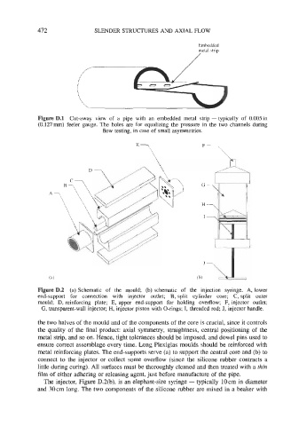
Figure D.l Cut-away view of a pipe with an embedded metal strip - typically of 0.005in
(0.127mm) feeler gauge. The holes are for equalizing the pressure in the two channels during
flow testing, in case of small asymmetries.
F- _4:
E?\
G
H
I
Figure D.2 (a) Schematic of the mould; (b) schematic of the injection syringe. A, lower
end-support for connection with injector outlet; B, split cylinder core; C, split outer
mould; D, reinforcing plate; E, upper end-support for holding overilow; F, injector outlet;
G, transparent-wall injector; H, injector piston with O-rings; I, threaded rod; J, injector handle.
the two halves of the mould and of the components of the core is crucial, since it controls
the quality of the final product: axial symmetry, straightness, central positioning of the
metal strip, and so on. Hence, tight tolerances should be imposed, and dowel pins used to
ensure correct assemblage every time. Long Plexiglas moulds should be reinforced with
metal reinforcing plates. The end-supports serve (a) to support the central core and (b) to
connect to the injector or collect some overflow (since the silicone rubber contracts a
little during curing). All surfaces must be thoroughly cleaned and then treated with a thin
film of either adhering or releasing agent, just before manufacture of the pipe.
The injector, Figure D.2(b), is an elephant-size syringe - typically IOcm in diameter
and 30cm long. The two components of the silicone rubber are mixed in a beaker with