
Page 139 - Fluid mechanics, heat transfer, and mass transfer
P. 139
PUMPS 117
& Avoiding liquid vortex formation in suction side
vessel/tank: Installing sturdy vortex breakers firmly
anchored to the vessel should be considered.
& Keeping liquid velocities in suction line below
1–2 m/s.
& Reducing liquid temperatures by cooling before
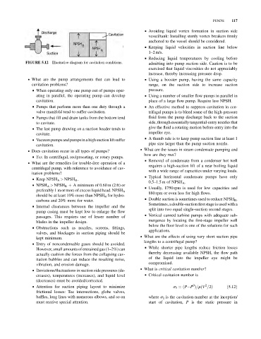
FIGURE 5.12 Illustrative diagram for cavitation conditions. admitting into pump suction side. Caution is to be
exercised that liquid viscosities do not appreciably
increase, thereby increasing pressure drop.
. What are the pump arrangements that can lead to & Using a booster pump, having the same capacity
cavitation problems? range, on the suction side to increase suction
& When operating only one pump out of pumps oper- pressure.
ating in parallel, the operating pump can develop & Using a number of smaller flow pumps in parallel in
cavitation. place of a large flow pump. Require less NPSH.
& Pumps that perform more than one duty through a & An effective method to suppress cavitation in cen-
valve manifold tend to suffer cavitation. trifugal pumps is to bleed some of the high-pressure
& Pumps that fill and drain tanks from the bottom tend fluid from the pump discharge back to the suction
to cavitate. side, through essentially tangential-entry nozzles that
& The last pump drawing on a suction header tends to give the fluid a rotating motion before entry into the
cavitate. impeller eye.
& A thumb rule is to keep pump suction line at least 1
& Vacuum pumps and pumps in a high suction lift suffer
cavitation. pipe size larger than the pump suction nozzle.
. What are the issues in steam condensate pumping and
. Does cavitation occur in all types of pumps?
how are they met?
& Yes. In centrifugal, reciprocating, or rotary pumps.
& Removal of condensate from a condenser hot well
. What are the remedies for trouble-free operation of a
requires a high-suction lift of a near boiling liquid
centrifugal pump, with reference to avoidance of cav-
with a wide range of capacities under varying loads.
itation problems?
& Typical horizontal condensate pumps have only
& Keep NPSH A > NPSH R .
0.5–1.5 m of NPSH A .
& NPSH A > NPSH R þ A minimum of 0.60 m (2 ft) or
& Usually, 1750 rpm is used for low capacities and
preferably 1 m or more of excess liquid head. NPSH A
880 rpm or even less for high flows.
should be at least 10% more than NPSH R for hydro-
& Double suction is sometimes used to reduce NPSH R .
carbons and 20% more for water.
Sometimes, a double-suction first stage is used with a
& Internal clearances between the impeller and the
split into two equal single-suction second stages.
pump casing must be kept low to enlarge the flow
& Vertical canned turbine pumps with adequate sub-
passages. This requires use of lesser number of
mergence by locating the first-stage impeller well
blades in the impeller design.
below the floor level is one of the solutions for such
& Obstructions such as nozzles, screens, fittings,
applications.
valves, and blockages in suction piping should be
kept minimum. . What are the effects of using very short suction pipe
lengths to a centrifugal pump?
& Entry of noncondensable gases should be avoided.
& While shorter pipe lengths reduce friction losses
However, small amounts of entrained gas (1–2%) can
actually cushion the forces from the collapsing cav- thereby decreasing available NPSH, the flow path
itation bubbles and can reduce the resulting noise, of the liquid into the impeller eye might be
vibration, and erosion damage. compromised.
. What is critical cavitation number?
& Deviations/fluctuations in suction side pressures (de-
creases), temperatures (increases), and liquid level & Critical cavitation number is
(decreases) must be avoided/corrected.
0
2
& Attention for suction piping layout to minimize s I ¼ðP P Þ=rðV =2Þ ð5:12Þ
frictional losses: Tee intersections, globe valves,
baffles, long lines with numerous elbows, and so on where s I is the cavitation number at the inception/
must receive special attention. start of cavitation, P is the static pressure in