
Page 190 - Fluid mechanics, heat transfer, and mass transfer
P. 190
MIXING
168
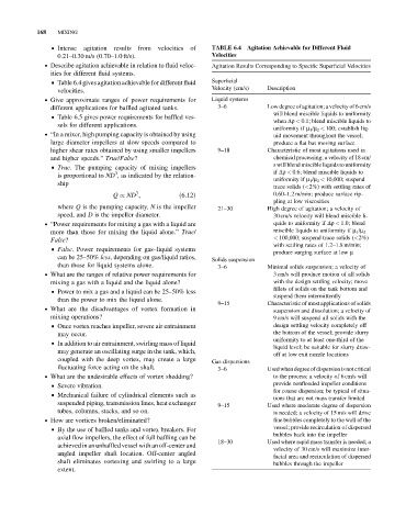
& Intense agitation results from velocities of TABLE 6.4 Agitation Achievable for Different Fluid
0.21–0.30 m/s (0.70–1.0 ft/s). Velocities
. Describe agitation achievable in relation to fluid veloc- Agitation Results Corresponding to Specific Superficial Velocities
ities for different fluid systems.
& Table 6.4 givesagitation achievable for different fluid Superficial
velocities. Velocity (cm/s) Description
. Give approximate ranges of power requirements for Liquid systems
different applications for baffled agitated tanks. 3–6 Low degree of agitation; a velocity of 6 cm/s
will blend miscible liquids to uniformity
& Table 6.5 gives power requirements for baffled ves-
when Dr < 0.1; blend miscible liquids to
sels for different applications.
uniformity if m 1 /m 2 < 100; establish liq-
. “In a mixer, high pumping capacity is obtained by using uid movement throughout the vessel;
large diameter impellers at slow speeds compared to produce a flat but moving surface
higher shear rates obtained by using smaller impellers 9–18 Characteristic of most agitations used in
and higher speeds.” True/False? chemical processing; a velocity of 18 cm/
s will blend miscible liquids to uniformity
& True. The pumping capacity of mixing impellers
3
is proportional to ND , as indicated by the relation- if Dr < 0.6; blend miscible liquids to
uniformity if m 1 /m 2 < 10,000; suspend
ship
trace solids (<2%) with settling rates of
3
Q / ND ; ð6:12Þ 0.60–1.2 m/min; produce surface rip-
pling at low viscosities
where Q is the pumping capacity, N is the impeller 21–30 High degree of agitation; a velocity of
speed, and D is the impeller diameter. 30 cm/s velocity will blend miscible li-
. “Power requirements for mixing a gas with a liquid are quids to uniformity if Dr < 1.0; blend
more than those for mixing the liquid alone.” True/ miscible liquids to uniformity if m 1 /m 2
False? < 100,000; suspend trace solids (<2%)
with settling rates of 1.2–1.8 m/min;
& False. Power requirements for gas–liquid systems
produce surging surface at low m
can be 25–50% less, depending on gas/liquid ratios, Solids suspension
than those for liquid systems alone. 3–6 Minimal solids suspension; a velocity of
. What are the ranges of relative power requirements for 3 cm/s will produce motion of all solids
mixing a gas with a liquid and the liquid alone? with the design settling velocity; move
fillets of solids on the tank bottom and
& Power to mix a gas and a liquid can be 25–50% less
suspend them intermittently
than the power to mix the liquid alone.
9–15 Characteristic of most applications of solids
. What are the disadvantages of vortex formation in
suspension and dissolution; a velocity of
mixing operations? 9 cm/s will suspend all solids with the
& Once vortex reaches impeller, severe air entrainment design settling velocity completely off
may occur. the bottom of the vessel; provide slurry
uniformity to at least one-third of the
& In addition to air entrainment, swirling mass of liquid
liquid level; be suitable for slurry draw-
may generate an oscillating surge in the tank, which,
off at low exit nozzle locations
coupled with the deep vortex, may create a large Gas dispersions
fluctuating force acting on the shaft. 3–6 Usedwhendegree of dispersion is not critical
. What are the undesirable effects of vortex shedding? to the process; a velocity of 6 cm/s will
& Severe vibration. provide nonflooded impeller conditions
for coarse dispersion; be typical of situa-
& Mechanical failure of cylindrical elements such as
tions that are not mass transfer limited
suspended piping, transmission lines, heat exchanger 9–15 Used where moderate degree of dispersion
tubes, columns, stacks, and so on. is needed; a velocity of 15 m/s will drive
. How are vortices broken/eliminated? fine bubbles completely to the wall of the
& By the use of baffled tanks and vortex breakers. For vessel; provide recirculation of dispersed
bubbles back into the impeller
axial flow impellers, the effect of full baffling can be
18–30 Used where rapid mass transfer is needed; a
achieved in an unbaffled vessel with an off-center and
velocity of 30 cm/s will maximize inter-
angled impeller shaft location. Off-center angled
facial area and recirculation of dispersed
shaft eliminates vortexing and swirling to a large bubbles through the impeller
extent.