
Page 195 - Fluid mechanics, heat transfer, and mass transfer
P. 195
MIXING EQUIPMENT 173
& Impellers can be divided into two general classes,
axial flow/hydrofoil or radial flow, depending on the
angle the blade makes with the axis of the drive
shaft.
& Axial flow and hydrofoil impellers make an angle
of less than 90 with the mixer shaft. Axial flow
impellers are used at high speeds to promote rapid
dispersion and used at low speeds for keeping solids
in suspension. The impellers tend to have high flow
rates and low shear rates. Often used with low-
viscosity fluids (<1000 cP). In most cases, baffling
is required for the optimal performance of this
impeller design. Examples of axial flow impellers
include the marine propeller, fan turbine, and
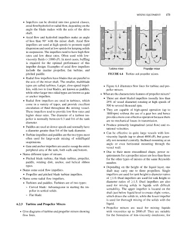
pitched paddle. FIGURE 6.4 Turbine and propeller mixers.
& Radial flow impellers have blades that are parallel to
the axis of the mixer shaft. The smaller, multiblade
types are called turbines. Larger, slow-speed impel- & Figure 6.4 illustrates flow lines for turbine and pro-
lers, with two to four blades, are known as paddles, peller mixers.
while other larger two-sided types are known as gate . What are the characteristic features of propeller mixers?
or anchor impellers.
& These are short bladed impellers (usually less than
& Radial flow impellers are used in turbines, which
25% of vessel diameter) rotating at high speeds of
come in a variety of types, and provide excellent 500 to several thousand rpm.
circulation of fluid throughout the mixing vessel.
& They are capable of high-speed operation (up to
These impellers tend to provide low flow rates and
1800 rpm) without the use of a gear box and hence
higher shear rates. The diameter of a turbine im-
providea more cost-effectiveoperation because there
peller is normally between 0.3 and 0.6 of the tank
are no mechanical losses in transmission.
diameter.
& Produce primarily longitudinal (axial flow) and ro-
& Paddles are used at slower speeds and normally have
tational velocities.
a diameter greater than 0.6 of the tank diameter.
& Can be effective in quite large vessels with low-
& Turbine impellers and paddles are the two types most
viscosity liquids (up to about 4000 cP), but gener-
often used for large-scale mixing of solid/liquid
ally not mounted centrally. Inclined mounting at an
suspensions.
angle or even horizontal mounting through the
& Gate and anchor impellers are used to sweep the entire
vessel wall.
peripheral area of the tank, both walls and bottom.
& Due to their more streamlined shape, power re-
. Name different types of mixers.
quirements for a propeller mixer are less than those
& Pitched blade turbine, flat blade turbine, propeller,
for the other types of mixers at the same Reynolds
paddle, rotating disk, anchor, and helical ribbon number.
types. & Depending on the height of the liquid layer, one
. Name some axial flow impellers. shaft may carry one to three propellers. Single
& Propeller and pitched blade turbine impellers. impellers are used for tank height to diameter ratios
. Name some radial flow impellers. of 1.0. Dual impellers are used for tank height to
diameter ratios of 1.5. Duel impellers are also
& Turbines and paddles. Turbines are of two types:
used for mixing solids in liquids with difficult
➢ Curved blade: Advantageous in starting the im-
wettability. The upper impeller is located on the
peller in settled solids.
shaft just below liquid level to create slight vortex,
➢ Flat blade.
which draws the solids in, while the lower impeller
is used for thorough mixing of the solids with the
liquid.
6.2.3 Turbine and Propeller Mixers
& Propeller mixers are used for mixing liquids
. Give diagrams of turbine and propeller mixers showing with viscosities up to 2000 cP. They are suitable
flow lines. for the formation of low-viscosity emulsions, for