
Page 198 - Fluid mechanics, heat transfer, and mass transfer
P. 198
MIXING
176
These distances are based on the viscosity of the
6.2.4 Paddle Mixers
mixture.
. What are the types and characteristic features of paddle
& For mixing liquids with viscosities up to 1000 cP, as
mixers?
well as for heated tanks in cases in which sedimen-
& Paddle mixers consist of two or more blades mounted
tation can occur, anchor or gate paddle mixers are
on a vertical or inclined shaft.
employed. For such applications, paddle diameters
& Speeds normally are in the range of 20–50 rpm.
are almost as large as the inside diameter of the tank
Under these conditions, mixing action is small and
so that the outer and bottom edges of the paddle
vortex formation is prevented.
scrape or clean the walls and bottom.
& Paddle mixers are often used in vessels without
& Leaf-shaped (broad blade) paddle mixers provide a
baffles. In broad blade paddles, which operate at
predominanttangentialflowofliquid,butthereisalso
speeds up to 120 rpm, baffles are incorporated into
turbulence at the upper and lower edges of the blade.
the design to minimize vortex formation.
These are employedfor mixing low-viscosity liquids,
& Commonly used paddles are of half to three quarters
intensifyingheattransferprocesses,promotingchem-
the diameter of the vessel with width of the blades 1/ ical reactions in a reactor, and dissolving materials.
10th to 1/6th of their length. & Not easily fouled.
& Consist of high radial and rotational components.
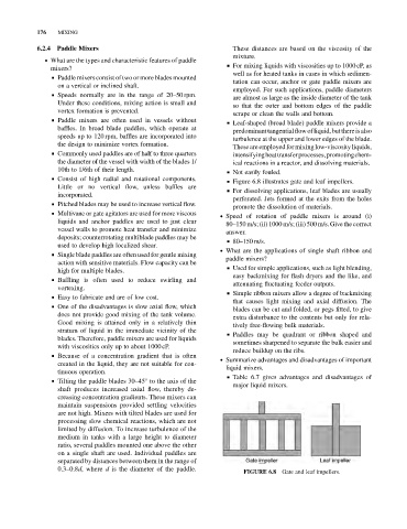
& Figure 6.8 illustrates gate and leaf impellers.
Little or no vertical flow, unless baffles are
& For dissolving applications, leaf blades are usually
incorporated.
perforated. Jets formed at the exits from the holes
& Pitched blades may be used to increase vertical flow.
promote the dissolution of materials.
& Multivane or gate agitators are used for more viscous
. Speed of rotation of paddle mixers is around (i)
liquids and anchor paddles are used to just clear
80–150 m/s; (ii) 1000 m/s; (iii) 500 m/s. Give the correct
vessel walls to promote heat transfer and minimize
answer.
deposits; counterrotating multiblade paddles may be
& 80–150 m/s.
used to develop high localized shear.
. What are the applications of single shaft ribbon and
& Single blade paddles are often used for gentle mixing
paddle mixers?
action with sensitive materials. Flow capacity can be
& Used for simple applications, such as light blending,
high for multiple blades.
easy backmixing for flash dryers and the like, and
& Baffling is often used to reduce swirling and
attenuating fluctuating feeder outputs.
vortexing.
& Simple ribbon mixers allow a degree of backmixing
& Easy to fabricate and are of low cost.
that causes light mixing and axial diffusion. The
& One of the disadvantages is slow axial flow, which
blades can be cut and folded, or pegs fitted, to give
does not provide good mixing of the tank volume.
extra disturbance to the contents but only for rela-
Good mixing is attained only in a relatively thin
tively free-flowing bulk materials.
stratum of liquid in the immediate vicinity of the
& Paddles may be quadrant or ribbon shaped and
blades. Therefore, paddle mixers are used for liquids
sometimes sharpened to separate the bulk easier and
with viscosities only up to about 1000 cP.
reduce buildup on the ribs.
& Because of a concentration gradient that is often
. Summarize advantages and disadvantages of important
created in the liquid, they are not suitable for con-
liquid mixers.
tinuous operation.
& Table 6.7 gives advantages and disadvantages of
& Tilting the paddle blades 30–45 to the axis of the
major liquid mixers.
shaft produces increased axial flow, thereby de-
creasing concentration gradients. These mixers can
maintain suspensions provided settling velocities
are not high. Mixers with tilted blades are used for
processing slow chemical reactions, which are not
limited by diffusion. To increase turbulence of the
medium in tanks with a large height to diameter
ratio, several paddles mounted one above the other
on a single shaft are used. Individual paddles are
separated by distances between them in the range of
0.3–0.8d,where d is the diameter of the paddle.
FIGURE 6.8 Gate and leaf impellers.