Page 194 - Fluid mechanics, heat transfer, and mass transfer
P. 194

MIXING
            172
            TABLE 6.6  Power Input and Impeller Tip Speeds for Baffled Tanks
                                                    Power Requirements                          Tip Speeds
                                                   3
            Process                           (kW/m )             (hp/1000 gal)           (m/s)             (ft/s)
            Blending                        0.033–0.082             0.2–0.5                –                  –
            Homogeneous reaction            0.082–0.247             0.5–1.5             2.29–3.05           7.5–10
            Reaction with heat transfer     0.247–0.824             1.5–5.0             3.05–4.57           10–15
            Liquid–liquid mixtures          0.824                   5.0                 4.57–6.09           15–20
            Liquid–gas mixtures             0.824–1.647              5–10               4.57–6.09           15–20
            Slurries                        1.647                   10                     –                  –


               . What is the important problem in the use of flat plate  ➢ Not more than two baffles are fitted this way due to
                baffles? What is the alternative?                         space limitations.
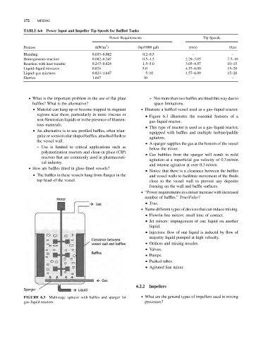
                 & Material can hang up or become trapped in stagnant  . Illustrate a baffled vessel used as a gas–liquid reactor.
                  regions near them, particularly in more viscous or  & Figure 6.3 illustrates the essential features of a
                  non-Newtonian liquids or in the presence of filamen-
                                                                       gas–liquid reactor.
                  tous materials.
                                                                     & This type of reactor is used as a gas–liquid reactor,
                 & An alternative is to use profiled baffles, often trian-
                                                                       equipped with baffles and multiple turbine/paddle
                  gular or semicircular shaped baffles, attached flush to
                                                                       agitators.
                  the vessel wall.
                                                                     & A sparger supplies the gas at the bottom of the vessel
                  ➢ Use is limited to critical applications such as
                                                                       below the mixer.
                    polymerization reactors and clean-in-place (CIP)
                                                                     & Gas bubbles from the sparger will result in mild
                    reactors that are commonly used in pharmaceuti-
                                                                       agitation at a superficial gas velocity of 0.3 m/min
                    cal industry.
                                                                       and intense agitation at over 0.3 m/min.
               . How are baffles fitted in glass-lined vessels?
                                                                     & Notice that there is a clearance between the baffles
                 & The baffles in these vessels hang from flanges in the
                                                                       and vessel walls to facilitate movement of the fluids
                  top head of the vessel.                              close to the vessel wall to prevent any deposits
                                                                       forming on the wall and baffle surfaces.
                                                                   . “Power requirements in a mixer increase with increased
                                                                     number of baffles.” True/False?
                                                                     & True.
                                                                   . Name different types of devices that can induce mixing.
                                                                     & Flow/in-line mixers: small time of contact.
                                                                     & Jet mixers: impingement of one liquid on another
                                                                       liquid.
                                                                     & Injectors: flow of one liquid is induced by flow of
                                                                       majority liquid pumped at high velocity.
                                                                     & Orifices and mixing nozzles.
                                                                     & Valves.
                                                                     & Pumps.
                                                                     & Packed tubes.
                                                                     & Agitated line mixer.


                                                                 6.2.2  Impellers
                        Multistage agitator with baffles and sparger for  . What are the general types of impellers used in mixing
            FIGURE 6.3
            gas–liquid reactors.                                     processes?
   189   190   191   192   193   194   195   196   197   198   199