
Page 94 - Fluid mechanics, heat transfer, and mass transfer
P. 94
FLOW MEASUREMENT 71
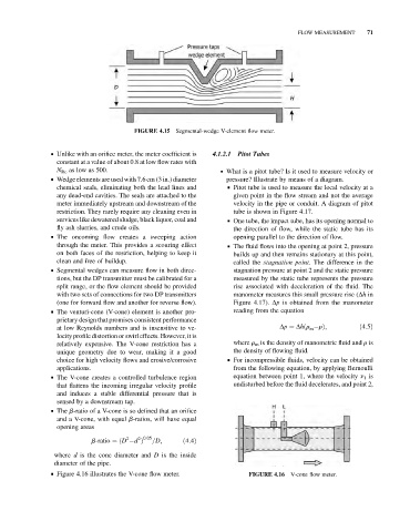
FIGURE 4.15 Segmental-wedge V-element flow meter.
& Unlike with an orifice meter, the meter coefficient is 4.1.2.1 Pitot Tubes
constant at a value of about 0.8 at low flow rates with
N Re as low as 500. . What is a pitot tube? Is it used to measure velocity or
& Wedge elements are used with 7.6 cm (3 in.) diameter pressure? Illustrate by means of a diagram.
chemical seals, eliminating both the lead lines and & Pitot tube is used to measure the local velocity at a
any dead-end cavities. The seals are attached to the given point in the flow stream and not the average
meter immediately upstream and downstream of the velocity in the pipe or conduit. A diagram of pitot
restriction. They rarely require any cleaning even in tube is shown in Figure 4.17.
services like dewatered sludge, black liquor, coal and & One tube, the impact tube, has its opening normal to
fly ash slurries, and crude oils. the direction of flow, while the static tube has its
& The oncoming flow creates a sweeping action opening parallel to the direction of flow.
through the meter. This provides a scouring effect & The fluid flows into the opening at point 2, pressure
on both faces of the restriction, helping to keep it builds up and then remains stationary at this point,
clean and free of buildup. called the stagnation point. The difference in the
& Segmental wedges can measure flow in both direc- stagnation pressure at point 2 and the static pressure
tions, but the DP transmitter must be calibrated for a measured by the static tube represents the pressure
split range, or the flow element should be provided rise associated with deceleration of the fluid. The
with two sets of connections for two DP transmitters manometer measures this small pressure rise (Dh in
(one for forward flow and another for reverse flow). Figure 4.17). Dp is obtained from the manometer
& The venturi-cone (V-cone) element is another pro- reading from the equation
prietary design that promises consistent performance
at low Reynolds numbers and is insensitive to ve- Dp ¼ Dhðr rÞ; ð4:5Þ
m
locity profile distortion or swirl effects. However, it is
relatively expensive. The V-cone restriction has a where r m is the density of manometric fluid and r is
unique geometry due to wear, making it a good the density of flowing fluid.
choice for high velocity flows and erosive/corrosive & For incompressible fluids, velocity can be obtained
applications. from the following equation, by applying Bernoulli
& The V-cone creates a controlled turbulence region equation between point 1, where the velocity n 1 is
that flattens the incoming irregular velocity profile undisturbed before the fluid decelerates, and point 2,
and induces a stable differential pressure that is
sensed by a downstream tap.
& The b-ratio of a V-cone is so defined that an orifice
and a V-cone, with equal b-ratios, will have equal
opening areas
2 2 0:05
b-ratio ¼ðD d Þ =D; ð4:4Þ
where d is the cone diameter and D is the inside
diameter of the pipe.
& Figure 4.16 illustrates the V-cone flow meter. FIGURE 4.16 V-cone flow meter.