
Page 95 - Fluid mechanics, heat transfer, and mass transfer
P. 95
FLOW MEASUREMENT
72
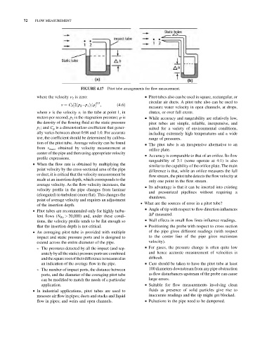
FIGURE 4.17 Pitot tube arrangements for flow measurement.
where the velocity n 2 is zero: & Pitot tubes also can be used in square, rectangular, or
circular air ducts. A pitot tube also can be used to
0:5
v ¼ C P ½2ðp 2 p 1 Þ=r ; ð4:6Þ
measure water velocity in open channels, at drops,
where n is the velocity v 1 in the tube at point 1, in chutes, or over fall crests.
meters per second; p 2 is the stagnation pressure; r is & While accuracy and rangeability are relatively low,
the density of the flowing fluid at the static pressure pitot tubes are simple, reliable, inexpensive, and
p 1 ; and C p is a dimensionless coefficient that gener- suited for a variety of environmental conditions,
ally varies between about 0.98 and 1.0. For accurate including extremely high temperatures and a wide
use, the coefficient should be determined by calibra- range of pressures.
tion of the pitot tube. Average velocity can be found & The pitot tube is an inexpensive alternative to an
from v max , obtained by velocity measurement at
orifice plate.
center of the pipe and then using appropriate velocity
& Accuracy is comparable to that of an orifice. Its flow
profile expressions.
rangeability of 3:1 (some operate at 4:1) is also
& When the flow rate is obtained by multiplying the
similar to the capability of the orifice plate. The main
point velocity by the cross-sectional area of the pipe
difference is that, while an orifice measures the full
or duct, it is critical that the velocity measurement be
flow stream, the pitot tube detects the flow velocity at
made at an insertion depth, which corresponds to the only one point in the flow stream.
average velocity. As the flow velocity increases, the
& Its advantage is that it can be inserted into existing
velocity profile in the pipe changes from laminar
and pressurized pipelines without requiring a
(elongated) to turbulent (more flat). This changes the
shutdown.
point of average velocity and requires an adjustment
. What are the sources of error in a pitot tube?
of the insertion depth.
& Angle of tip with respect to flow direction influences
& Pitot tubes are recommended only for highly turbu-
DP measured.
lent flows (N Re > 20,000) and, under these condi-
tions, the velocity profile tends to be flat enough so & Wall effects in small flow lines influence readings.
that the insertion depth is not critical. & Positioning the probe with respect to cross section
& An averaging pitot tube is provided with multiple of the pipe gives different readings (with respect
impact and static pressure ports and is designed to to the center line of the pipe gives maximum
extend across the entire diameter of the pipe. velocity).
➢ The pressures detected by all the impact (and sep- & For gases, the pressure change is often quite low
arately byall the static) pressureports are combined and hence accurate measurement of velocities is
andthesquarerootoftheirdifferenceismeasuredas difficult.
an indication of the average flow in the pipe. & Care should be taken to have the pitot tube at least
➢ The number of impact ports, the distance between 100 diameters downstream from any pipe obstruction
ports, and the diameter of the averaging pitot tube as flow disturbances upstream of the probe can cause
can be modified to match the needs of a particular large errors.
application. & Suitable for flow measurements involving clean
& In industrial applications, pitot tubes are used to fluids as presence of solid particles give rise to
measure air flow in pipes; ducts and stacks and liquid inaccurate readings and the tip might get blocked.
flow in pipes; and weirs and open channels. & Pulsations in the pipe need to be dampened.