
Page 116 - Fluid-Structure Interactions Slender Structure and Axial Flow (Volume 1)
P. 116
98 SLENDER STRUCTURES AND AXIAL FLOW
at u2/n2 2: 6.2, followed by coupled-mode flutter at point C (u2/n2 2: 7), in this case via
a Hamiltonian Hopf bifurcation. The value of u for restabilization at point I3 corresponds
exactly to the point where the nongyroscopic system, or indeed the pipe systems in (a)
and (b), develop divergence in their second mode.
In closing, the following two important points should be made. First, the results of
Figures 3.9-3.11, 3.14 and 3.15 apply equally to pipes with a downstream end either free
to slide axially or not [Figure 3.l(a,b)]: since linear theory cannot distinguish between
the two, the same equation governs both; however, the foregoing explanation of the
existence of coupled-mode flutter applies only to systems with a sliding end. Second, and
as cautioned at the outset, the existence of coupled-mode flutter has to be decided by
nonlinear theory (Chapter 5) and by experiments (Section 3.4.4).
3.4.2 Pressurization, tensioning and gravity effects
If dissipative and gravity effects are neglected and dU/dt = 0, equation (3.38) simpli-
fies to
+
a2w
a4w
EZ - [MU2 + pA(1- 2~6) - TI a2w + 2MU - (M + M)- a2w = 0, (3.98)
f
~
ax4 ax2 axat at2
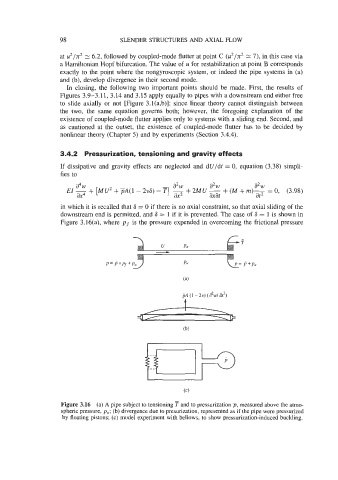
in which it is recalled that 6 = 0 if there is no axial constraint, so that axial sliding of the
downstream end is permitted, and 6 = 1 if it is prevented. The case of S = 1 is shown in
Figure 3.16(a), where pf is the pressure expended in overcoming the frictional pressure
-
u PO T
J=
P= P+Pf +PO
Figure 3.16 (a) A pipe subject to tensioning T and to pressurization p, measured above the atmo-
spheric pressure, pa; (b) divergence due to presurization, represented as if the pipe were pressurized
by floating pistons; (c) model experiment with bellows, to show pressurization-induced buckling.